
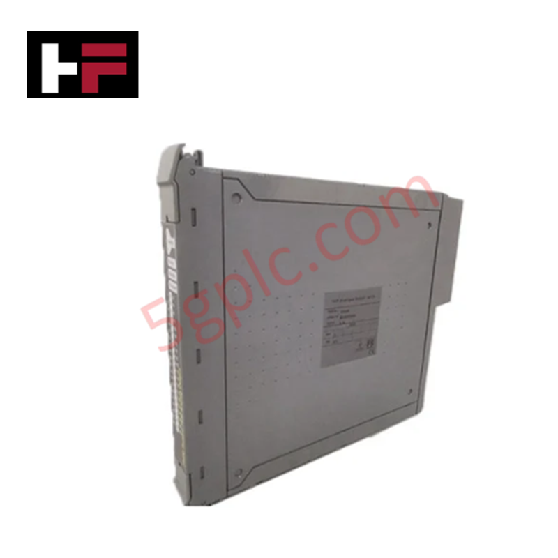
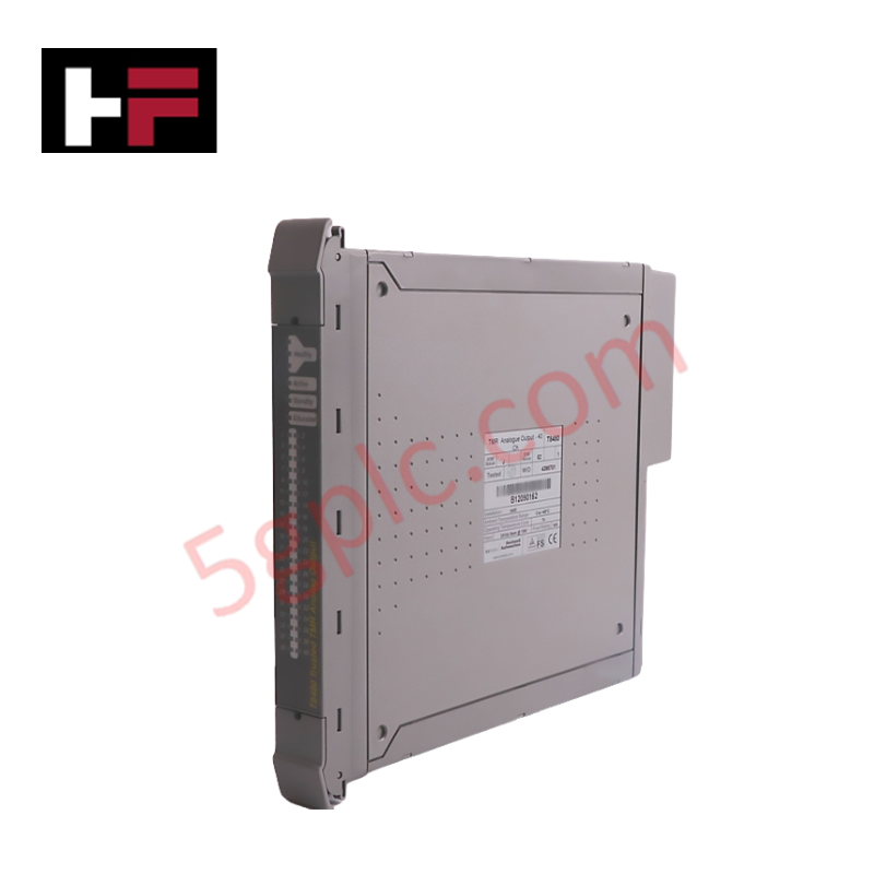
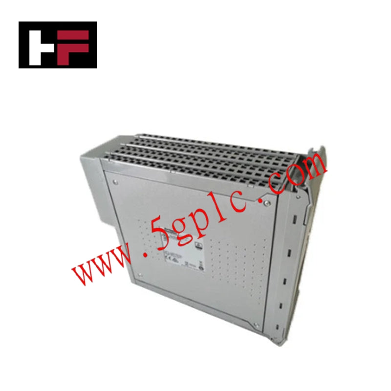
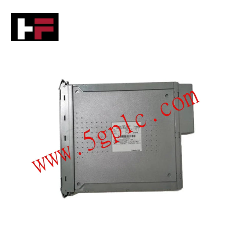


Product Details
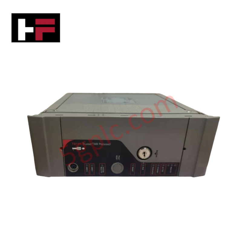
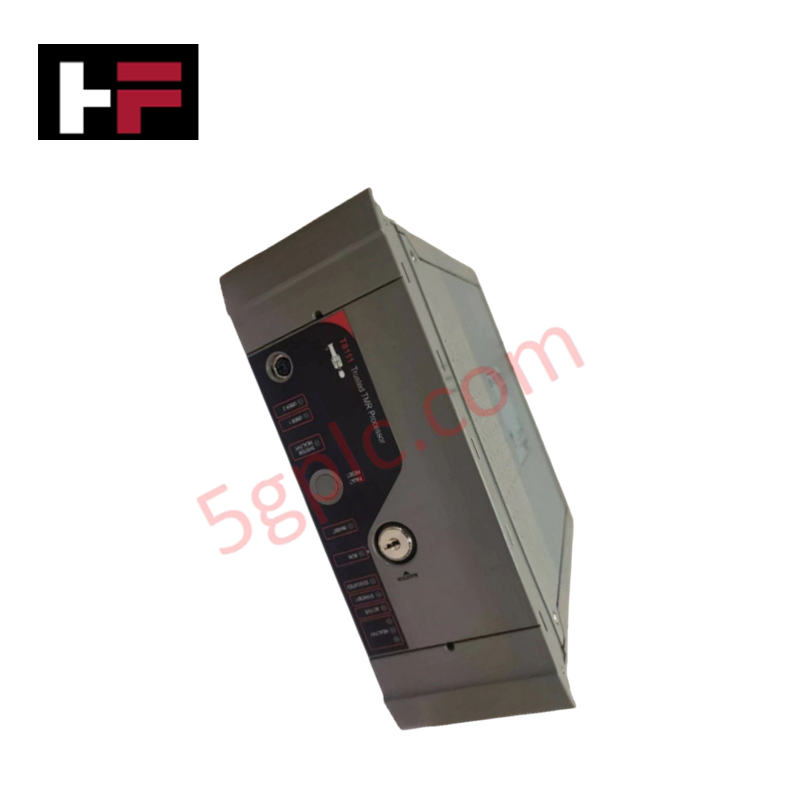
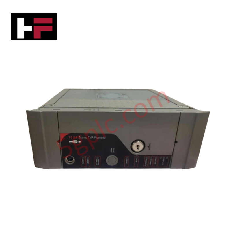
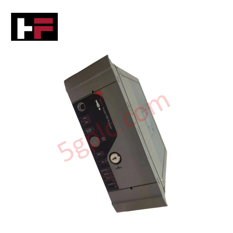
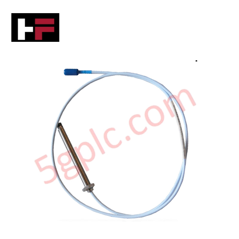
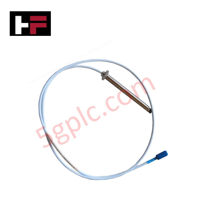
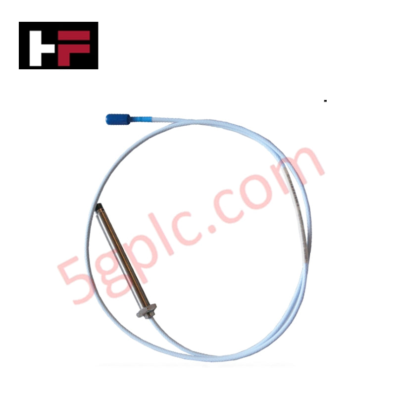
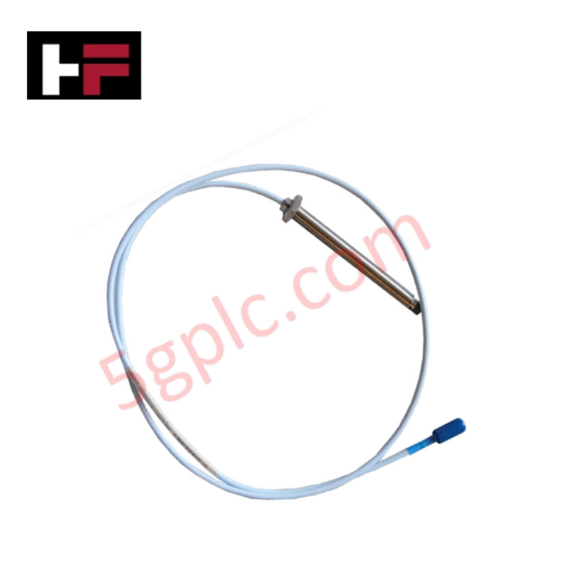
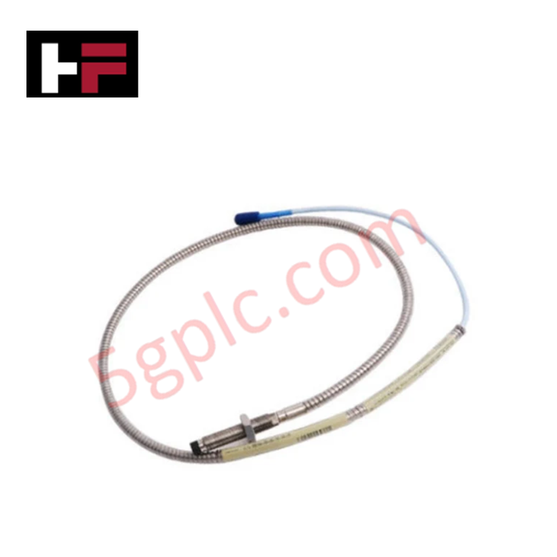
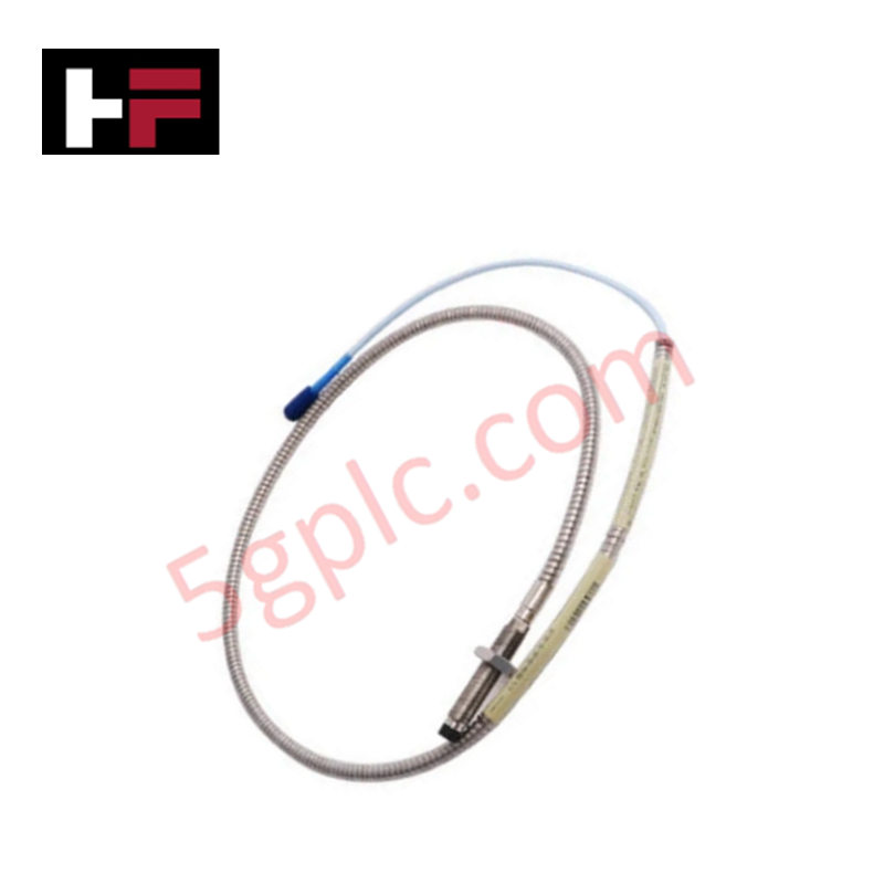
The Bently Nevada 330103-00-04-05-02-05 is a 3300 XL 8 mm eddy-current proximity probe with an M10 x 1 thread, 0 mm unthreaded length, 40 mm case length, and 0.5 m total length. Equipped with a miniature coaxial ClickLoc connector and CSA, ATEX, and IECEx approvals, it provides non-contacting displacement and vibration sensing on rotating machinery.
Design and Signal Performance
Within a 3300 XL transducer system, the probe measures non-contacting displacement between the tip and a conductive target to support shaft vibration, axial position, and speed monitoring, with a standard system scale factor of 200 mV/mil (7.87 V/mm). Its mechanical configuration, linear range, and accuracy align with API 670 standards, and it includes improved RFI/EMI immunity.
Construction features include TipLoc and CableLoc designs rated for up to 330 N (75 lbf) pull strength, paired with a miniature coaxial ClickLoc connector with gold-plated contacts. Confirm exact component interchangeability and backward compatibility with 3300 series 5 mm and 8 mm parts against the specific system configuration before mixing hardware.
Installation Guidelines
- Thread the M10 x 1 body cleanly into the mounting bracket or housing.
- Keep a minimum clear radius of 30 mm (1.2 in) around the probe tip and observe metal-free zone rules so the eddy-current RF field is not distorted.
- Space adjacent probe tips at least 40 mm (1.6 in) apart to prevent signal crosstalk.
- Handle the probe tip carefully and power down the system before connecting or disconnecting cables.
- Verify CSA, ATEX, and IECEx hazardous area requirements and site permits before installation.
Hardware Specifications
| Parameter | Specification |
|---|---|
| Model | 330103-00-04-05-02-05 |
| Brand | Bently Nevada |
| Sensing Principle | Eddy-current |
| Probe Diameter | 8 mm |
| Thread Size | M10 x 1 |
| Unthreaded Length | 0 mm |
| Case Length | 40 mm |
| Total Length | 0.5 m |
| Connector Type | Miniature coaxial ClickLoc (gold-plated contacts) |
| Pull Strength | 330 N (75 lbf) |
| Standard Scale Factor Sensitivity | 200 mV/mil (7.87 V/mm) |
| Approvals | CSA, ATEX, IECEx |
Frequently Asked Questions
Q: What is the primary function of the 330103-00-04-05-02-05 probe?
A: It provides non-contacting measurement of static shaft position and dynamic shaft vibration using eddy-current sensing within a compatible 3300 XL transducer channel.
Q: Does this 0.5 m probe require an extension cable?
A: Yes, because the total probe length is 0.5 m, it is paired with a compatible 3300 XL extension cable to reach the Proximitor sensor according to system length rules.
Q: What minimum clearance is required around the probe tip and between adjacent probes?
A: Maintain a minimum clear radius of 30 mm (1.2 in) around the probe tip, observe metal-free zone requirements, and keep adjacent probe tips at least 40 mm (1.6 in) apart to avoid crosstalk.
Additional Information
- 100% Genuine Parts: All products are original and authentic, ensuring reliable industrial performance.
- 30-Day Refund Guarantee: Return any in-stock item within 30 days in original, unopened packaging for a full refund (excluding shipping and fees).
- 12-Month Warranty: Covers defects in materials or workmanship; excludes misuse, normal wear, or unauthorized modifications.
- Worldwide Shipping: We ship via USPS, UPS, FedEx, and DHL. Delivery times vary by country and may be subject to customs or import fees.
- Support & Contact: Technical and warranty assistance is available anytime. Contact us here: Contact.
- Purchase Guidance: Check product specifications and compatibility carefully before ordering to ensure proper application.


Tech & Buying Guide
Essential Guide to Grounding Electronic Equipment in Industrial Automation
Industrial automation systems require robust grounding for personal safety and fault clearance. Safety grounding minimizes touch potential across exposed metallic enclosures. It ensures rapid clearance of fuses during electrical faults. However, electronic equipment introduces unique performance requirements. Solid-state devices operate at high speeds. Therefore, they exhibit extreme sensitivity to minor voltage transients. Facility engineers must balance electrical safety with operational signal integrity.

Engineering Guide to Selecting Electrical Earthing and Grounding Components in Industrial Automation
The overall reliability of any industrial automation network relies heavily on its grounding components. Control systems, PLCs, and distributed control systems (DCS) require rigorous earthing to mitigate electrical noise and faults. Engineers must select each component with extreme care. Furthermore, proper interconnection methods dictate whether a facility operates safely or suffers from chronic signal disruption.

Mastering Electrical Ground Loop Mitigation in Industrial Automation and Control Systems
Ground loops represent one of the most persistent challenges in industrial automation, PLC networks, and distributed control systems (DCS). According to IEEE Std. 100-1991, a ground loop forms when two or more points nominally at ground potential connect through a conducting path, creating potential differences. In sensitive analog and digital signal circuits, this unwanted conductive path allows noise currents to superimpose directly onto process signals.