


Product Details
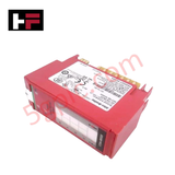
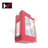
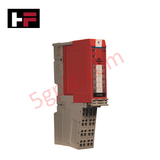
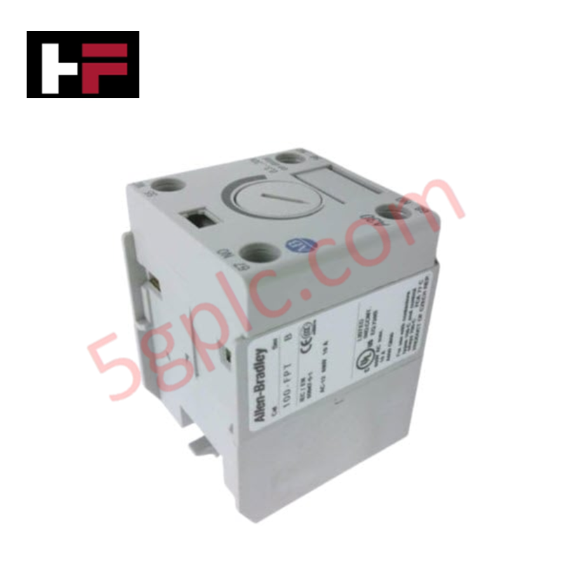
Configured for safety-rated output control in distributed I/O systems, the Allen-Bradley 1734-OBV2S (1734-OBV2S Safety Output Module) provides direct physical/electrical execution of dual-channel bipolar output logic across CIP Safety networks.
Hardware Specifications
| Parameter | Specification |
|---|---|
| Model | 1734-OBV2S |
| Brand | Allen-Bradley |
| Origin | USA |
| Output Type | 4 Bipolar Outputs (2 Pairs) |
| System Interface | POINT I/O Backplane |
Profinet / EtherNet/IP Deterministic Networks
The 1734-OBV2S integrates into EtherNet/IP deterministic networks via the POINT I/O adapter, utilizing CIP Safety protocol to maintain system-wide safety integrity. The module architecture supports I/O density scaling by allowing localized safety logic execution, which minimizes wiring complexity and optimizes network bandwidth usage. Firmware flash compatibility is managed through the Studio 5000 Logix Designer environment, ensuring the module adheres to the required safety function versioning. The bipolar output configuration allows for both source and sink load management, providing the necessary diagnostic coverage for safety-rated actuators.
Frequently Asked Questions
Q: Can this module be hot-swapped while the backplane is powered?
A: The module supports removal and insertion under power (RIUP) only when the specific POINT I/O base is rated for hot-swapping. However, any safety-rated output will transition to a de-energized state upon module removal, necessitating a system-level reset of the safety controller.
Q: Is external feedback required for the bipolar outputs?
A: The 1734-OBV2S performs internal diagnostics on its bipolar output pairs to verify state transitions. External feedback loops are optional unless required by the specific safety function's risk assessment to achieve a higher Performance Level (PL) or Safety Integrity Level (SIL).
Field Installation Guidelines
- Mount the 1734-OBV2S module onto a compatible POINT I/O terminal base; ensure the mechanical locking tab is fully engaged to maintain backplane communication.
- Verify that the terminal base address and wiring configuration match the safety controller project mapping to prevent output mapping errors.
- Use shielded cabling for all safety-rated output runs to mitigate electromagnetic interference and ensure the integrity of the diagnostic pulse signals.
- Terminate the 24 VDC power supply to the appropriate terminals on the base, observing the required voltage range to ensure reliable switching performance.
- Apply ferrules to stranded wires to ensure a secure, low-resistance connection within the spring-clamp or screw terminals.
- Conduct a full system validation test, including all safety-rated output transitions, to verify proper operation within the defined safety logic prior to standard production cycles.
Additional Information
- 100% Genuine Parts: All products are original and authentic, ensuring reliable industrial performance.
- 30-Day Refund Guarantee: Return any in-stock item within 30 days in original, unopened packaging for a full refund (excluding shipping and fees).
- 12-Month Warranty: Covers defects in materials or workmanship; excludes misuse, normal wear, or unauthorized modifications.
- Worldwide Shipping: We ship via USPS, UPS, FedEx, and DHL. Delivery times vary by country and may be subject to customs or import fees.
- Support & Contact: Technical and warranty assistance is available anytime. Contact us here: Contact.
- Purchase Guidance: Check product specifications and compatibility carefully before ordering to ensure proper application.


Tech & Buying Guide

Essential Motion Control Commands: A Practical Guide for Engineers
Automation engineers often rely on precise position and speed control to drive modern factory machinery. Modern industrial systems, such as Programmable Logic Controllers (PLCs) and Distributed Control Systems (DCS), depend heavily on standardized motion instructions. Mastering these commands ensures operational safety, protects mechanical components, and optimizes cycle times across production lines.

The Role of Intrinsic Safety Barriers in PLC and DCS Architectures
Implementing robust protection in hazardous industrial environments represents a fundamental safety requirement in factory automation. Process facilities often handle volatile gases, dusts, and chemical agents that pose significant combustion risks. Consequently, control system engineers must deploy energy-limiting interfaces to isolate safe-area control cabinets from hazardous-area field instrumentation. This article examines the function, selection, and electrical principles of intrinsic safety barriers within modern PLC and DCS networks.

Architectural Selection and Scale Classification of PLC Systems in Industrial Automation
Selecting the correct control platform represents a foundational engineering decision in factory automation. System designers must carefully balance technical parameters against long-term operational requirements when implementing a Programmable Logic Controller (PLC). This article examines the critical evaluation metrics, physical scale classifications, and operational architectures of modern control systems.