










Product Details
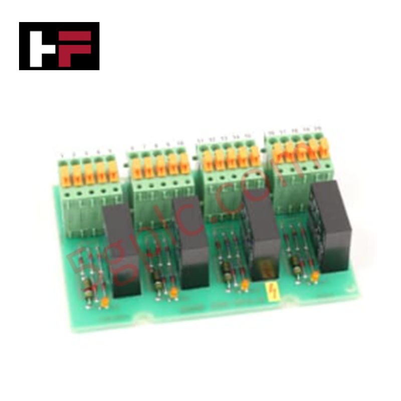
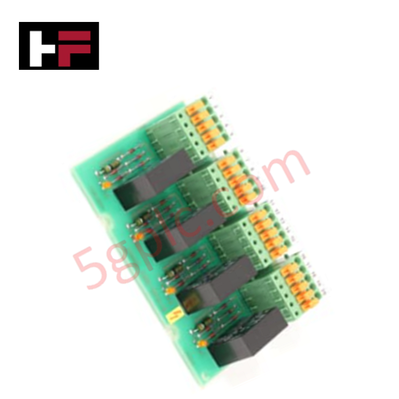
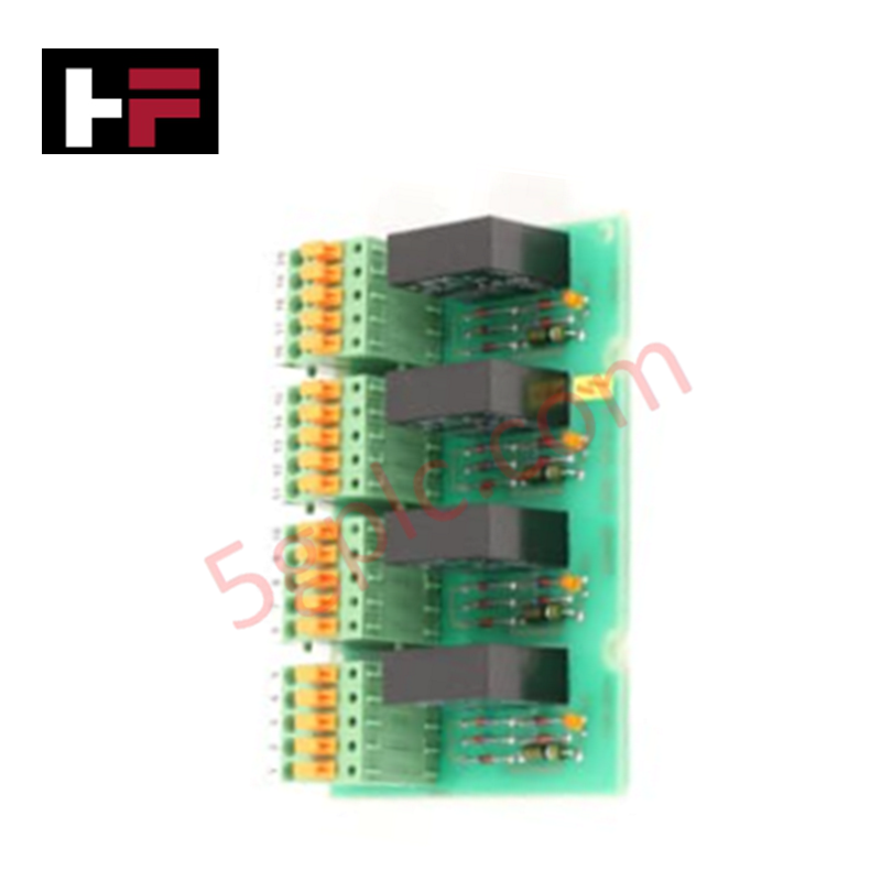
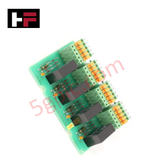
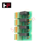
Configured for specialized contact switching functions in industrial control networks, the ABB PFVK 108 (PFVK 108 Relay Board) provides direct physical/electrical execution. Operating as a dedicated hardware module, this component routes binary command signals between internal processing backplanes and field actuator circuits via localized contact sets driven by an on-board 24 VDC voltage supply loop.
Hardware Specifications
| Parameter | Specification |
|---|---|
| Model | PFVK 108 (YM110001-SH) |
| Brand | ABB |
| Origin | Sweden |
| Weight | 0.205 kg |
| Dimensions | 120 mm x 80 mm (Substrate area) |
| Operating Temp | 0 to 60 deg C |
| Power Consumption | Nominally powered by 24 VDC supply |
| Part Type | Relay Board (Spare Parts Classification) |
| Customs Tariff Number | 85389091 |
| WEEE Category | Product Not in WEEE Scope |
Profinet / EtherNet/IP Deterministic Networks and I/O Density Scaling
The execution latency of the ABB PFVK 108 is timed to match localized backplane bus communication velocity constraints within high-density control racks. By decoupling the field inductive loops through independent relay sets, the board prevents electrical noise propagation from degrading downstream Profinet or EtherNet/IP deterministic networks. This isolation configuration protects logic processors during peak I/O density scaling phases, preventing data frame dropouts on the active communication channels and maintaining steady deterministic scan intervals across the system node map.
Frequently Asked Questions
Q: What are the primary diagnostic validation requirements before cycling the 24 VDC power supply to the board?
A: Check the input power wire polarity to make sure it aligns with the terminal markings. Verify that the combined inductive and resistive load assigned across the relay contacts does not surpass the nominal maximum safety limits of the micro-relays on the 120x80 mm substrate.
Q: Is this relay board rated for live insertion or extraction while the backplane bus is energized?
A: No. Hot-swapping the board when the 24 VDC power supply loop is live can introduce arc discharges across the power pins and trigger inductive voltage transients. This can cause fault trips or firmware lockups on adjacent digital modules within the same rack network segment.
Field Installation Guidelines
- DIN-Rail or Sub-Panel Mounting: Secure the board inside a dust-free enclosure using standard industrial standoffs or a compatible mounting base to fit the 120x80 mm dimensions. Ensure no mechanical flexing stress impacts the printed circuit board assembly.
- Wiring and Clearance: Maintain a distinct separation distance of at least 50 mm between the low-voltage 24 VDC supply inputs and any high-voltage field wiring connected to the relay switching output contacts.
- Inductive Load Suppression: Install flyback diodes for DC inductive loads or RC snubbers for AC inductive loads across the external field device terminals. This step suppresses voltage spikes during contact switching and extends terminal life.
- Shielding Compliance: Terminate any field signal line shields at the single-point instrument ground bus bar inside the enclosure. Do not form multiple ground connections to ensure ground loop currents are not generated.
Additional Information
- 100% Genuine Parts: All products are original and authentic, ensuring reliable industrial performance.
- 30-Day Refund Guarantee: Return any in-stock item within 30 days in original, unopened packaging for a full refund (excluding shipping and fees).
- 12-Month Warranty: Covers defects in materials or workmanship; excludes misuse, normal wear, or unauthorized modifications.
- Worldwide Shipping: We ship via USPS, UPS, FedEx, and DHL. Delivery times vary by country and may be subject to customs or import fees.
- Support & Contact: Technical and warranty assistance is available anytime. Contact us here: Contact.
- Purchase Guidance: Check product specifications and compatibility carefully before ordering to ensure proper application.









Tech & Buying Guide

Demystifying the DDE Protocol in Legacy Industrial Automation Systems
Modern control systems rely heavily on seamless interprocess communication to exchange operational data between software programs. Microsoft first introduced the Dynamic Data Exchange (DDE) protocol in 1987 to enable real-time data sharing. In factory automation, DDE served as an early bridge between control software and Windows desktop applications. Therefore, understanding DDE mechanics provides crucial insights into how legacy industrial networks established software-level connectivity.

Demystifying CPU Communication Ports in Siemens PLC Architectures
Industrial automation relies heavily on robust data exchange between devices. Without seamless connectivity, field instruments, network switches, human-machine interfaces, and programmable logic controllers cannot coordinate effectively. Therefore, understanding the various CPU communication ports available in Siemens hardware ensures efficient factory automation design and seamless system integration.

Mastering the Siemens PLC Scan Cycle: How the CPU Executes Automation Programs
Industrial automation relies heavily on programmable logic controllers (PLCs) to manage complex manufacturing processes. Many engineers dive straight into programming without mastering the underlying architecture. However, understanding how a PLC CPU executes a program ensures reliable system design. Therefore, mastering the scan cycle optimizes both performance and troubleshooting in modern control systems.