










Product Details
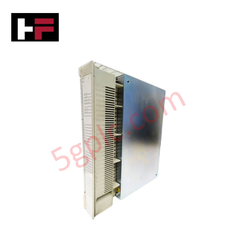
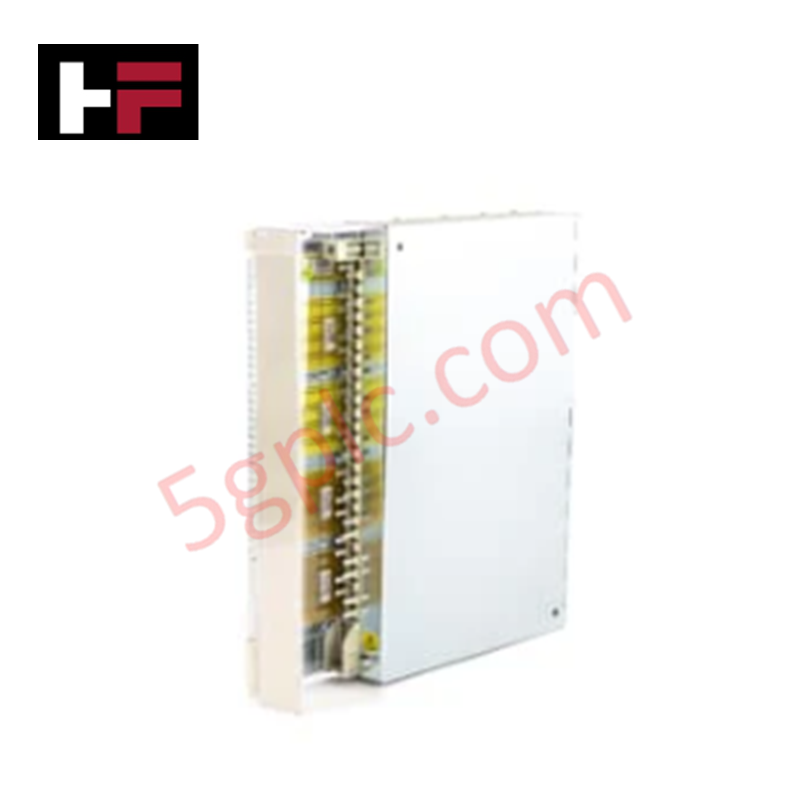
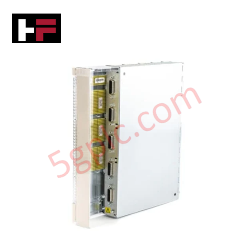
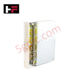
The ABB 3BHT300016R1, also cataloged as the DP620 I/O Module, operates as a dedicated hardware component for high-speed digital pulse frequency registration within ABB control system platforms.
Hardware Specifications
| Parameter | Specification |
|---|---|
| Model | 3BHT300016R1 (DP620) |
| Brand | ABB |
| Origin | Sweden |
| Weight | 1.635 kg |
| Dimensions | 252 mm (Depth) x 273 mm (Height) x 40 mm (Width) |
| Operating Temp | 0 to +55 deg C (Standard industrial parameters) |
| Power Consumption | Sourced via system backplane interface |
| Number of Channels | 5 independent pulse counter channels |
| Input Voltage Rating | 5 VDC / 24 VDC threshold ranges |
| Maximum Frequency | 100 kHz per channel |
| Channel Type | High-Speed Digital Input (DI) |
| Environmental Standards | RoHS compliant (EU Directive 2011/65/EU) |
| WEEE Category | 5-Small Equipment (No external dimension over 50 cm) |
Profinet / EtherNet/IP Deterministic Networks and I/O Density Scaling
The module functions as a local pulse processing board that offloads high-frequency counting tasks from the main processor, preventing reduction of the backplane bus communication velocity. The 5-channel sub-assembly converts incoming 100 kHz pulse patterns into binary integers directly accessible by the control loop software. This localization supports consistent I/O density scaling configurations across remote nodes linked via Profinet / EtherNet/IP deterministic networks, maintaining real-time tracking while ensuring strict firmware flash compatibility across standard automation racks.
Frequently Asked Questions
Q: How is the physical input threshold configured between 5 VDC and 24 VDC logic signals?
A: The input signal voltage thresholds are assigned via terminal wiring selection or software allocation. The hardware circuitry scales internal optocoupler saturation paths to safely match either standard 5 VDC TTL or 24 VDC industrial differential encoder outputs without risking terminal deterioration.
Q: What are the backplane constraints during a hot-swap occurrence of the DP620 card?
A: Physical insertion or extraction parameters depend on the hosting sub-rack specifications. The board must be completely isolated from high-speed pulse streams before extraction to prevent active counter register corruptions or voltage feedback transients on the system backplane logic lines.
Field Installation Guidelines
- Chassis Attachment: Slide the module vertically down the rack slot guides. Press firmly to ensure full backplane connector pin engagement before turning on power or tightening faceplate alignment fasteners.
- Shielding Protocol: Terminate the high-speed pulse cable shields to a dedicated ground bus bar near the point of entry in the enclosure cabinet. Do not daisy-chain shield grounds to minimize electromagnetic noise and signal reflection up to 100 kHz.
- Signal Cable Separations: Route 5 VDC and 24 VDC encoder or counter lines in independent low-voltage wiring trays. Maintain adequate physical spacing away from three-phase motor supply lines and inductive switching elements.
Additional Information
- 100% Genuine Parts: All products are original and authentic, ensuring reliable industrial performance.
- 30-Day Refund Guarantee: Return any in-stock item within 30 days in original, unopened packaging for a full refund (excluding shipping and fees).
- 12-Month Warranty: Covers defects in materials or workmanship; excludes misuse, normal wear, or unauthorized modifications.
- Worldwide Shipping: We ship via USPS, UPS, FedEx, and DHL. Delivery times vary by country and may be subject to customs or import fees.
- Support & Contact: Technical and warranty assistance is available anytime. Contact us here: Contact.
- Purchase Guidance: Check product specifications and compatibility carefully before ordering to ensure proper application.









Tech & Buying Guide

Demystifying the DDE Protocol in Legacy Industrial Automation Systems
Modern control systems rely heavily on seamless interprocess communication to exchange operational data between software programs. Microsoft first introduced the Dynamic Data Exchange (DDE) protocol in 1987 to enable real-time data sharing. In factory automation, DDE served as an early bridge between control software and Windows desktop applications. Therefore, understanding DDE mechanics provides crucial insights into how legacy industrial networks established software-level connectivity.

Demystifying CPU Communication Ports in Siemens PLC Architectures
Industrial automation relies heavily on robust data exchange between devices. Without seamless connectivity, field instruments, network switches, human-machine interfaces, and programmable logic controllers cannot coordinate effectively. Therefore, understanding the various CPU communication ports available in Siemens hardware ensures efficient factory automation design and seamless system integration.

Mastering the Siemens PLC Scan Cycle: How the CPU Executes Automation Programs
Industrial automation relies heavily on programmable logic controllers (PLCs) to manage complex manufacturing processes. Many engineers dive straight into programming without mastering the underlying architecture. However, understanding how a PLC CPU executes a program ensures reliable system design. Therefore, mastering the scan cycle optimizes both performance and troubleshooting in modern control systems.