












Product Details
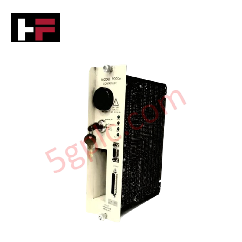
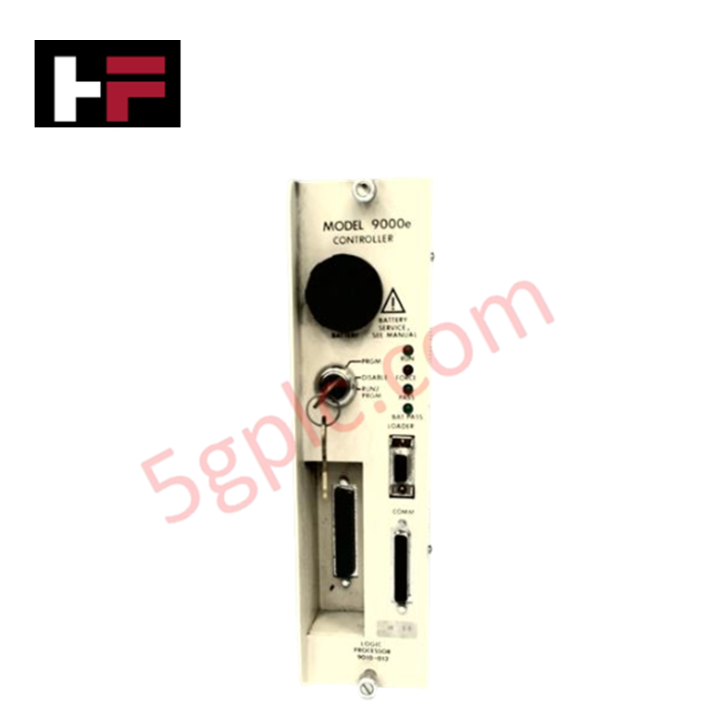
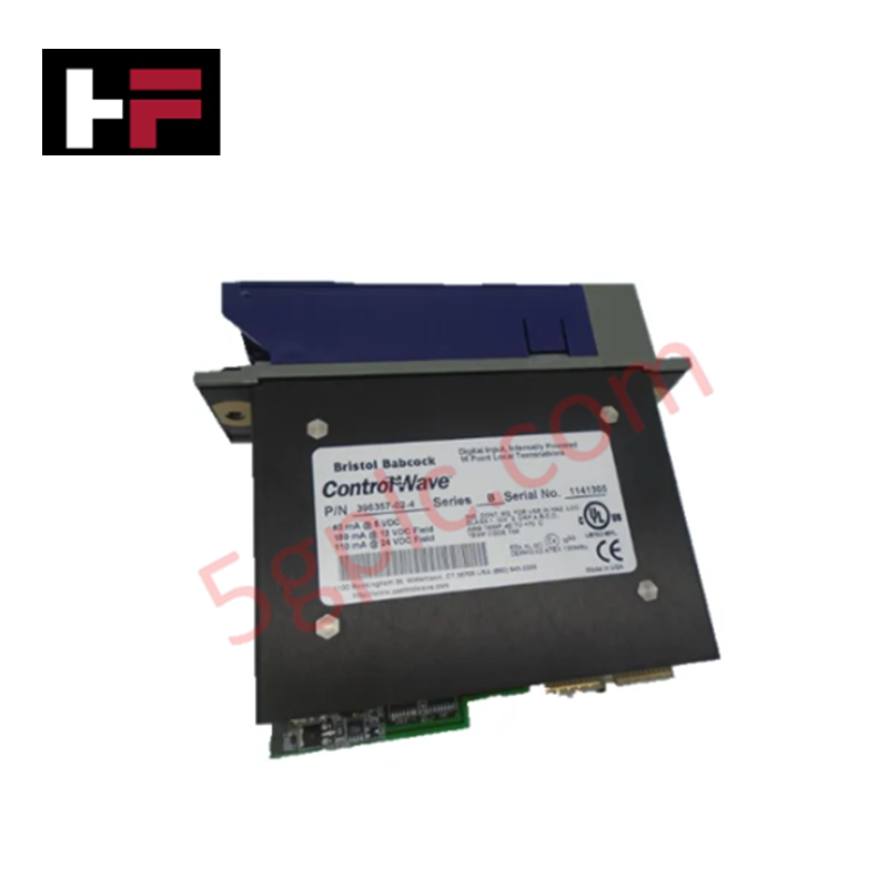
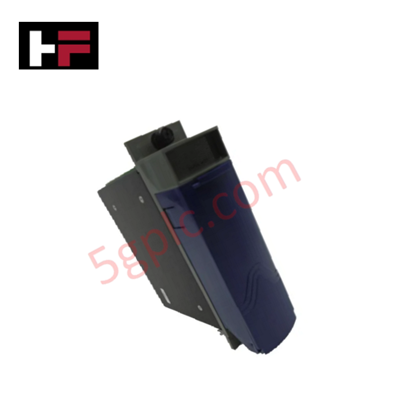
The Honeywell 9010-012, also cataloged as the 9010-012 Logic Processor Module, operates as a dedicated hardware component for deterministic logic execution and system status diagnostics within Honeywell S9000E control platforms.
Hardware Specifications
| Parameter | Specification |
|---|---|
| Model | 9010-012 |
| Brand | Honeywell |
| Origin | USA / Global Manufacturing |
| Weight | 1.20 lbs (0.54 kg) |
| Operating Temp | 0 to +60 deg C |
| Power Consumption | Powered via Backplane Bus |
| Module Type | VR 3.3 Logic Processor CPU Module |
| Series | S9000E |
| Interface / Control | Key Switch, Loader Port, Comm Port, Status LEDs |
4-20 mA HART Loop Protocol and Channel Isolation Conditioning
The 9010-012 logic processor module processes digital and analog data streams from field devices and I/O sub-racks across the internal backplane architecture. Onboard diagnostic routines continuously update front-panel status LEDs to reflect CPU health, memory integrity, and serial port activity during active scan execution.
Integrated communication pathways interface directly with external loader tools and serial network links via dedicated panel connections. When interfacing with process measurement loops, such as standard 4-20 mA HART loop protocol instruments or multi-channel transmitters, the unit relies on channel-to-channel isolation within I/O sub-modules to preserve signal integrity and protect CPU execution logic against common-mode electrical noise.
Frequently Asked Questions
Q: What front-panel diagnostic features are built into the 9010-012 CPU module?
A: The module features multi-state status LEDs for system diagnostics along with physical key switch controls for operating mode selection.
Q: How is external programming or loader hardware connected to the 9010-012 logic processor?
A: Connectivity is provided through the front-panel LOADER and COMM interface ports using standard serial communication assemblies.
Q: Is hot-swapping supported for the 9010-012 module while the S9000E rack is energized?
A: No, power to the rack backplane must be completely de-energized prior to inserting or removing the processor card to avoid hardware faults or bus disruption.
Field Installation Guidelines
- Verify that all backplane power sources are de-energized before inserting or removing the module from the sub-rack frame.
- Attach an ESD grounding wrist strap to the enclosure frame prior to handling the circuit board assembly.
- Ensure physical alignment along the card cage guide rails before seating the module backplane edge connectors.
- Torques all retaining thumb screws to secure the front panel against high-vibration industrial environments.
Additional Information
- 100% Genuine Parts: All products are original and authentic, ensuring reliable industrial performance.
- 30-Day Refund Guarantee: Return any in-stock item within 30 days in original, unopened packaging for a full refund (excluding shipping and fees).
- 12-Month Warranty: Covers defects in materials or workmanship; excludes misuse, normal wear, or unauthorized modifications.
- Worldwide Shipping: We ship via USPS, UPS, FedEx, and DHL. Delivery times vary by country and may be subject to customs or import fees.
- Support & Contact: Technical and warranty assistance is available anytime. Contact us here: Contact.
- Purchase Guidance: Check product specifications and compatibility carefully before ordering to ensure proper application.


Tech & Buying Guide
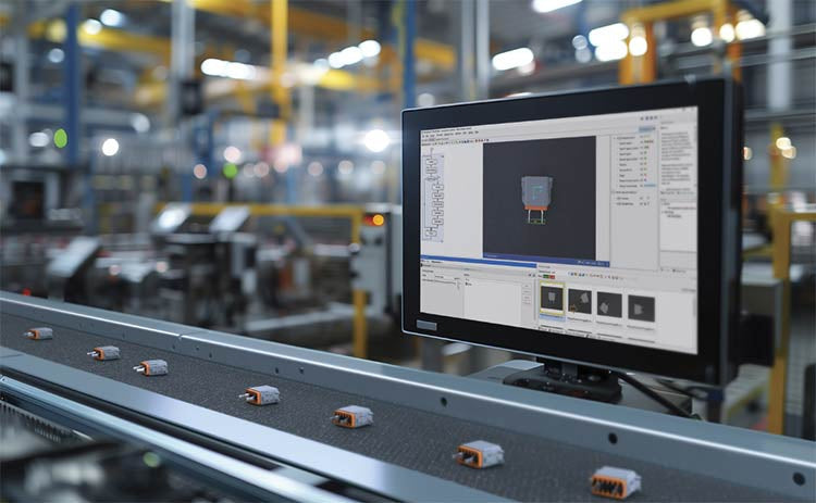
Modern Industrial Automation: Transforming Safety and Efficiency in Mining Operations
Industrial automation has evolved from a simple manufacturing tool into the operational backbone of high-risk sectors. Modern mining operations increasingly rely on advanced control systems, programmable logic controllers (PLCs), distributed control systems (DCS), and artificial intelligence to address deep-underground hazards. By replacing manual labor in high-risk zones, factory automation technologies protect personnel while significantly boosting operational throughput.

Step-by-Step System Cabinet Health Check Guide for PLC and DCS Infrastructure
