Product Details
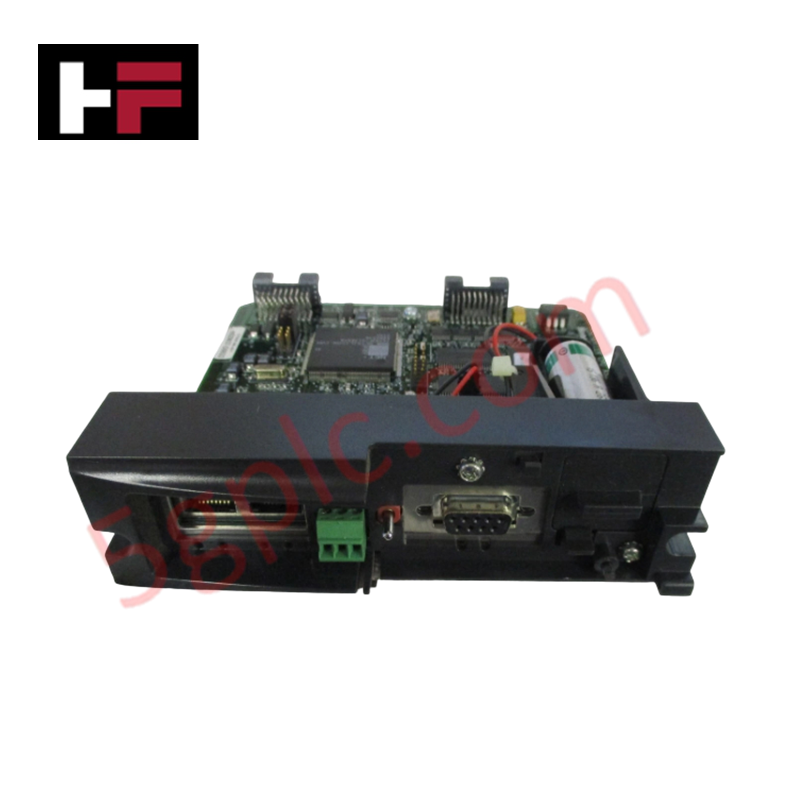
Configured for remote I/O data scanning and deterministic bus execution in Honeywell HC900 networks, the Honeywell 900C53-0124-00 (900C53-0124-00 I/O Scanner Module) provides direct physical/electrical execution.
Hardware Specifications
| Parameter | Specification |
|---|---|
| Model | 900C53-0124-00 |
| Brand | Honeywell |
| Origin | USA |
| Weight | 0.45 kg |
| Dimensions | Standard single-slot HC900 module format |
| Operating Temp | 0 to 60 deg C |
| Power Consumption | 5 VDC at 770 mA max (backplane) |
| Communication Protocol | IEEE 802.4 Ethernet (100Base-TX) |
| Addressing | DIP switch configurable rack addressing |
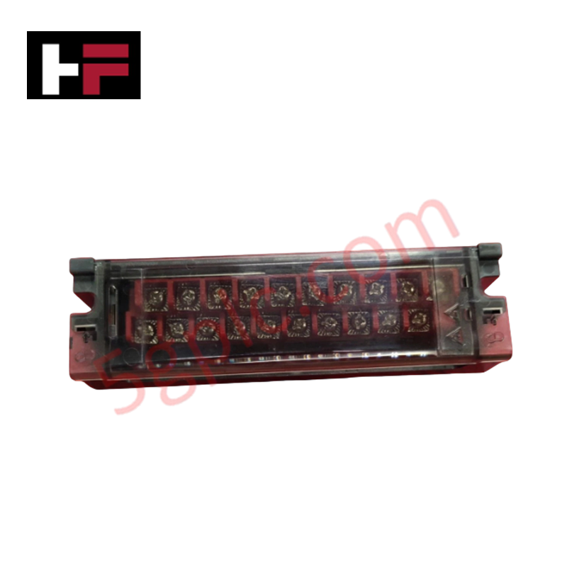
| Terminal Compatibility | Removable under logic power (field power disconnected) |
| Wire Gauge Limits | Barrier/Euro: #14 to #26 AWG; Euro specific: #12 to #26 AWG |
| Terminal Contacts | High Voltage: Red/Tin-coated; Low Voltage: Black/Gold-plated |
| Status LEDs | Module Status (Red/Green), Expansion I/O Port (Green/Yellow) |
Channel-to-Channel Isolation and Loop Diagnostics
The 900C53-0124-00 remote I/O scanner maintains real-time synchronization with the central controller scan cycle to multiplex digital and analog process values. Operating across 100Base-TX media, the module isolates local backplane signals while communicating with field instruments executing 4-20 mA HART loop protocol algorithms. High-grade channel-to-channel isolation and gold-plated terminal contacts on low-voltage lines prevent ground potential shifts and signal degradation, providing continuous bus verification and deterministic data transmission across distributed racks.
Frequently Asked Questions
Q: Can the 900C53-0124-00 terminal blocks be removed while backplane logic power is applied?
A: Terminal blocks are removable under power provided that all connected external field power sources are fully disconnected prior to removal.
Q: How is rack identification assigned on the 900C53-0124-00 scanner module?
A: Rack addressing is configured manually using hardware DIP switches located directly on the module body before insertion into the backplane.
Q: What do the front-panel status LEDs indicate during operation?
A: The Module Status LED uses Red/Green states to display operational modes or fault conditions, while the Expansion I/O Port LEDs use Green and Yellow states to show active receive/transmit bus activity.
Field Installation Guidelines
- Set the rack address DIP switches to match the assigned node position in the system configuration file prior to mounting.
- Align the 900C53-0124-00 module with the subrack guide rails and insert until the rear backplane connectors seat completely.
- Wire field inputs using approved #12 to #26 AWG solid or stranded conductors based on terminal block type (Red/Tin for High Voltage, Black/Gold for Low Voltage).
- Secure terminal blocks using integrated mounting fasteners to ensure continuous contact under physical vibration.
- De-energize all field power feeds before removing terminal block assemblies during routine maintenance.
Additional Information
- 100% Genuine Parts: All products are original and authentic, ensuring reliable industrial performance.
- 30-Day Refund Guarantee: Return any in-stock item within 30 days in original, unopened packaging for a full refund (excluding shipping and fees).
- 12-Month Warranty: Covers defects in materials or workmanship; excludes misuse, normal wear, or unauthorized modifications.
- Worldwide Shipping: We ship via USPS, UPS, FedEx, and DHL. Delivery times vary by country and may be subject to customs or import fees.
- Support & Contact: Technical and warranty assistance is available anytime. Contact us here: Contact.
- Purchase Guidance: Check product specifications and compatibility carefully before ordering to ensure proper application.





Tech & Buying Guide

Voice-Activated Industrial Automation: Integrating Speech Control into PLC and DCS Architectures
Industrial automation integrates speech recognition, IIoT protocols, and NLP with PLCs and DCS to streamline operations. By leveraging advanced edge computing, engineers enable real-time, hands-free control—allowing personnel to manage smart factory processes safely away from hazardous equipment.
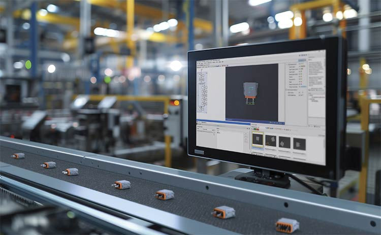
Modern Industrial Automation: Transforming Safety and Efficiency in Mining Operations
Industrial automation has evolved from a simple manufacturing tool into the operational backbone of high-risk sectors. Modern mining operations increasingly rely on advanced control systems, programmable logic controllers (PLCs), distributed control systems (DCS), and artificial intelligence to address deep-underground hazards. By replacing manual labor in high-risk zones, factory automation technologies protect personnel while significantly boosting operational throughput.