












Product Details
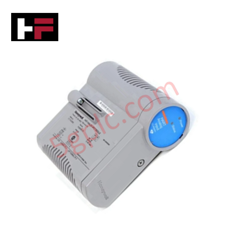
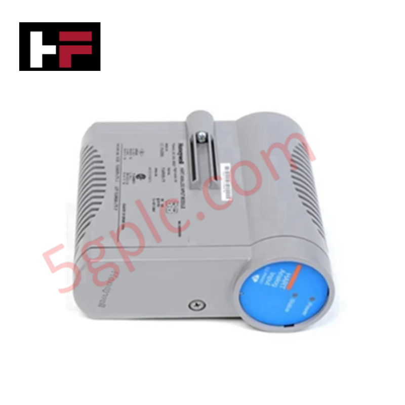
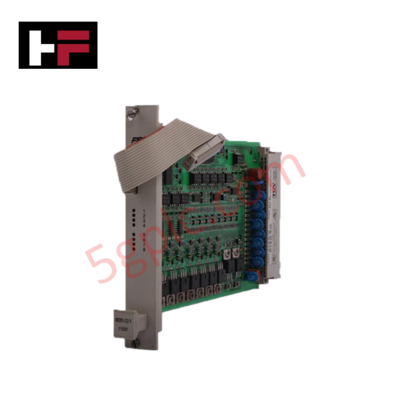
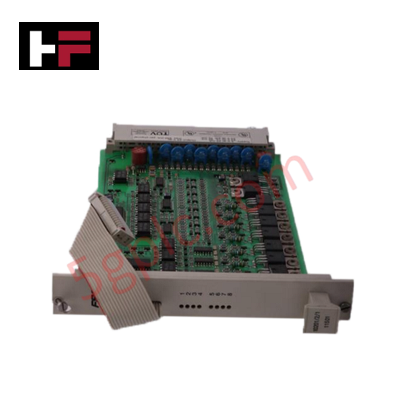
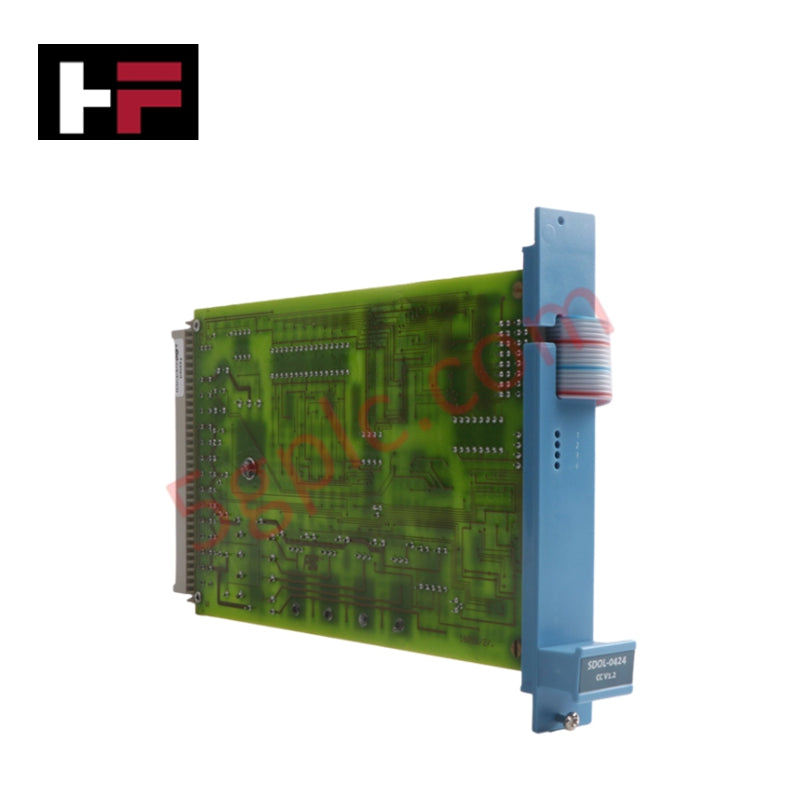
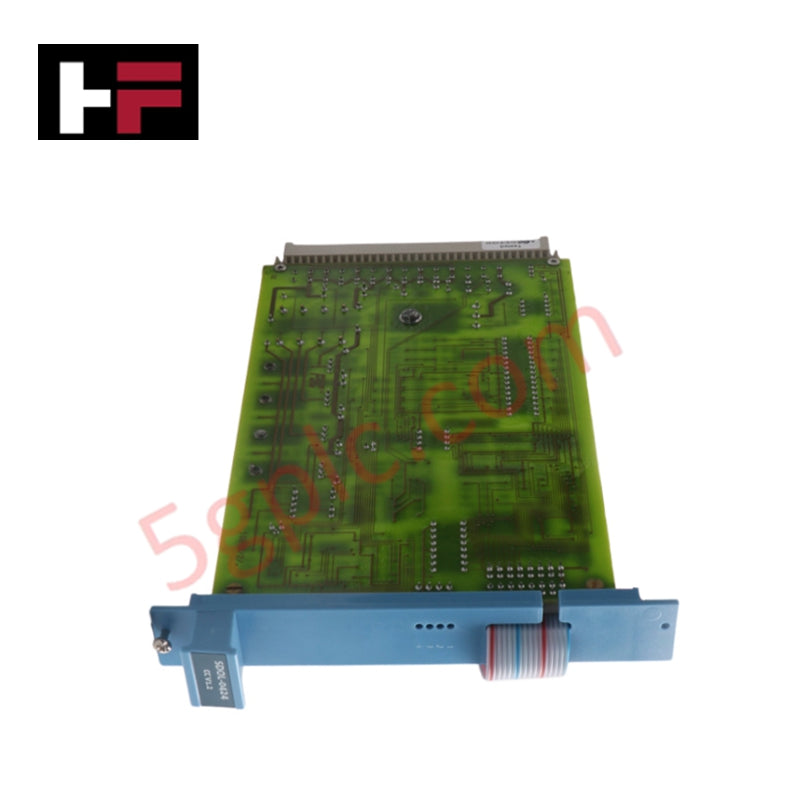
The Honeywell 8U-PWSP02-CN, also cataloged as the 8U-PWSP02-CN Digital Output Module, operates as a dedicated hardware component for field load switching and discrete channel excitation within Honeywell Experion PKS Series 8 platforms.
Hardware Specifications
| Parameter | Specification |
|---|---|
| Model | 8U-PWSP02-CN |
| Brand | Honeywell |
| Origin | USA |
| Weight | 2.0 kg (Shipping) |
| Output Voltage Range | 21 to 29 VDC |
| Continuous Current | 5 A maximum |
| Module Type | Digital Output Module |
Channel-to-Channel Isolation & 24 VDC Power Distribution
The module manages discrete output power distribution, driving relays, solenoid valves, and indicator circuits within an operating range of 21 to 29 VDC. Galvanic channel-to-channel isolation prevents transient electrical surges, ground potential shifts, and inductive switching spikes on field wiring from propagating to internal controller backplane buses. Integrated current-limiting safeguards maintain stable voltage levels across output circuits up to the continuous rating of 5 A.
Frequently Asked Questions
Q: What is the maximum continuous current capacity supported by the 8U-PWSP02-CN output circuits?
A: The module supports a maximum continuous current load of 5 A across its field power distribution terminals.
Q: What operating DC voltage range is permitted for connected field devices?
A: Field power supply lines connected to the module channels must remain within 21 to 29 VDC.
Q: How does the module prevent inductive field spikes from affecting central processing logic?
A: Galvanic isolation circuits separate field output lines from internal backplane logic, suppressing electrical transients and noise coupling.
Field Installation Guidelines
- Isolate power from the Series 8 carrier assembly or rack before seating or unseating the 8U-PWSP02-CN module.
- Wear an ESD grounding strap during module handling to protect internal semiconductor components from static discharge.
- Align the module card edge with the designated slot and press firmly until retention mechanisms latch completely.
- Route field output cabling in separate cable trays away from high-voltage AC lines to prevent inductive noise coupling.
- Terminate signal shields at a single ground bus bar and ensure field load currents remain within the maximum 5 A continuous specification.
Additional Information
- 100% Genuine Parts: All products are original and authentic, ensuring reliable industrial performance.
- 30-Day Refund Guarantee: Return any in-stock item within 30 days in original, unopened packaging for a full refund (excluding shipping and fees).
- 12-Month Warranty: Covers defects in materials or workmanship; excludes misuse, normal wear, or unauthorized modifications.
- Worldwide Shipping: We ship via USPS, UPS, FedEx, and DHL. Delivery times vary by country and may be subject to customs or import fees.
- Support & Contact: Technical and warranty assistance is available anytime. Contact us here: Contact.
- Purchase Guidance: Check product specifications and compatibility carefully before ordering to ensure proper application.




Tech & Buying Guide
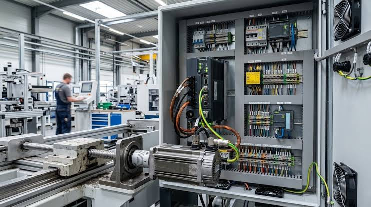
Demystifying Programmable Logic Controllers: Comprehensive Guide to PLC Classification and Selection in Industrial Automation
Modern industrial automation heavily relies on Programmable Logic Controllers (PLCs) to drive factory floor efficiency. Over my 15 years as an industrial automation expert working with DCS, TSI, and control systems, I have seen PLCs evolve into the central nervous system of modern manufacturing. Selecting the right controller requires a deep understanding of PLC types based on physical size, hardware architecture, and power supply configurations.
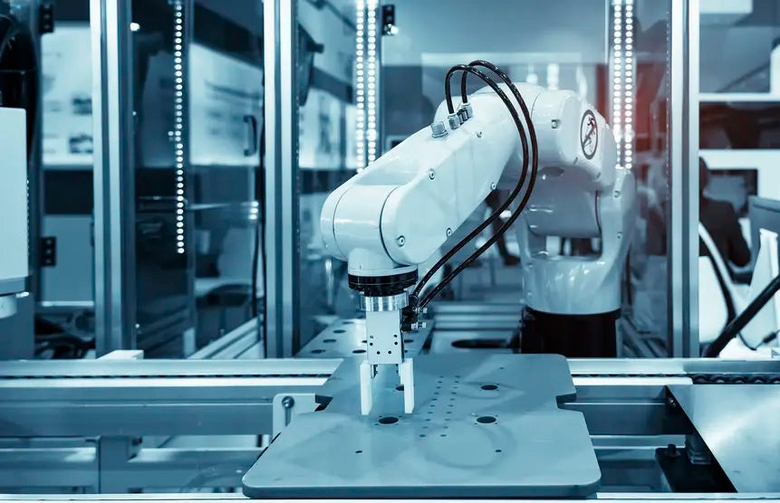
Comprehensive Guide to PLC Types in Modern Industrial Automation
Modern industrial automation relies on programmable logic controllers to govern critical factory operations. System integrators classify PLCs based on scale, hardware architecture, and power supply design. Understanding these core categories enables automation engineers to select the right control system architecture. Consequently, proper hardware selection optimizes performance while minimizing long-term operational costs.

Demystifying the DDE Protocol in Legacy Industrial Automation Systems
Modern control systems rely heavily on seamless interprocess communication to exchange operational data between software programs. Microsoft first introduced the Dynamic Data Exchange (DDE) protocol in 1987 to enable real-time data sharing. In factory automation, DDE served as an early bridge between control software and Windows desktop applications. Therefore, understanding DDE mechanics provides crucial insights into how legacy industrial networks established software-level connectivity.