


Product Details
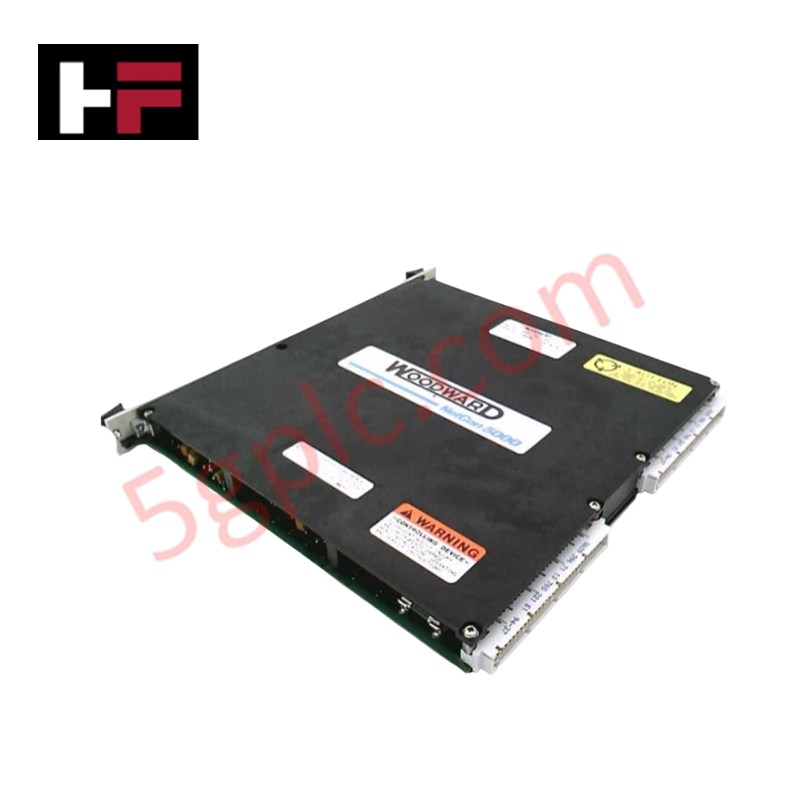
Configured for high-precision analog signal acquisition in turbine control platforms, the Woodward 5464-334 (5464-334 Analog Input Module) provides direct physical execution of isolated 4-20 mA current loop sensing and onboard diagnostic processing.
Hardware Specifications
| Parameter | Specification |
|---|---|
| Model | 5464-334 |
| Brand | Woodward |
| Origin | USA |
| Weight | 0.8 kg |
| Dimensions | 30 cm x 20 cm x 25 cm |
| Operating Temp | -25 deg C to +70 deg C |
| Power Consumption | 10-60 VDC |
| Channels | 8 Channels |
| Isolation | 3000 VDC |
Actuator Loop Feedback Response and Thermal Heat Sink Dissipation Profiles
The 5464-334 module utilizes an intelligent microcontroller architecture to manage 8 independent 4-20 mA input channels. Each channel maintains galvanic isolation to suppress common-mode noise and prevent cross-channel interference. To maintain signal integrity during continuous operation, the module's circuitry is engineered with specific thermal heat sink dissipation profiles, preventing localized overheating in the high-density terminal interface. This thermal management supports consistent actuator loop feedback response, as the module performs automated temperature compensation and calibration by periodically measuring an onboard precision voltage reference. The module independently handles rate-group scheduling, minimizing the processing overhead on the central CPU while ensuring deterministic signal acquisition and fault reporting.
Frequently Asked Questions
Q: How does the module handle internal fault detection for individual input channels?
A: The onboard microcontroller executes power-on self-tests and continuous background diagnostics. If a channel deviation is detected relative to the internal voltage reference or if an electrical fault occurs, the module illuminates the front-panel LED to signal the fault state to the operator.
Q: Is the 3000 VDC isolation rating applied channel-to-channel or channel-to-chassis?
A: The 3000 VDC isolation specification defines the dielectric strength between the input circuitry and the system ground/backplane. This level of isolation ensures that transients on the field side do not propagate to the control-side communication bus.
Field Installation Guidelines
- Mounting: Secure the module within the designated control rack, ensuring positive engagement with the backplane connectors. Verify that the cabinet environment remains within the -25 to +70 deg C range.
- Wiring: Terminate field loops using shielded, twisted-pair cabling. Maintain strict polarity for all 4-20 mA inputs to ensure correct transducer signal interpretation.
- Grounding: Connect cable shields to the cabinet ground bus at a single common point. Avoid multiple ground paths for the shield to prevent the induction of circulating currents that may interfere with the current loop precision.
- Power-up Procedure: Energize the control rack and observe the front-panel LED. Successful initialization occurs when the LED extinguishes following the completion of the onboard microcontroller self-tests.
Additional Information
- 100% Genuine Parts: All products are original and authentic, ensuring reliable industrial performance.
- 30-Day Refund Guarantee: Return any in-stock item within 30 days in original, unopened packaging for a full refund (excluding shipping and fees).
- 12-Month Warranty: Covers defects in materials or workmanship; excludes misuse, normal wear, or unauthorized modifications.
- Worldwide Shipping: We ship via USPS, UPS, FedEx, and DHL. Delivery times vary by country and may be subject to customs or import fees.
- Support & Contact: Technical and warranty assistance is available anytime. Contact us here: Contact.
- Purchase Guidance: Check product specifications and compatibility carefully before ordering to ensure proper application.


Tech & Buying Guide

Strategic Selection: Choosing the Right SCADA Software for Your PLC Project
In industrial automation, the SCADA (Supervisory Control and Data Acquisition) system acts as the bridge between raw machine data and actionable human intelligence. Selecting the incorrect software platform can lead to integration bottlenecks, scalability issues, and excessive long-term maintenance costs. As an automation consultant with 15 years of experience, I have guided many projects through the selection process. Below are the essential criteria for choosing a platform that ensures both performance and longevity.

Ensuring Operational Continuity: The Strategic Value of Redundant Automation Systems
In modern industrial landscapes, unplanned downtime is the ultimate adversary. For sectors relying on complex PLC and DCS architectures, a single hardware failure can trigger catastrophic production losses. Therefore, implementing redundant automation systems is no longer a luxury; it is a fundamental requirement for mission-critical operations. In this article, I analyze why redundancy remains the backbone of reliable industrial infrastructure.

Selecting the Right Cables for Industrial Automation: A Comprehensive Guide
Selecting the appropriate cabling infrastructure is critical for the success of any industrial automation project. Improper cable selection often leads to signal degradation, system instability, and costly downtime. As an automation engineer, I frequently see projects compromised by poor cabling choices in harsh industrial environments. This guide simplifies the complex landscape of cabling to help you make informed decisions for your PLC, DCS, and control systems.