


Product Details
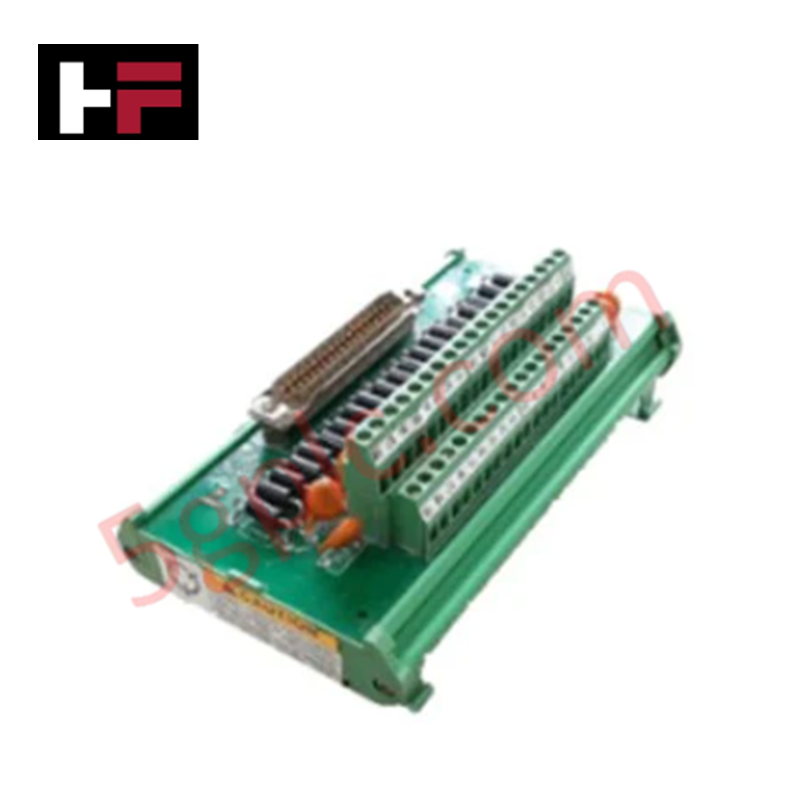
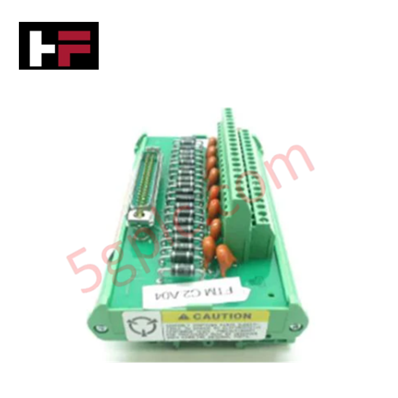
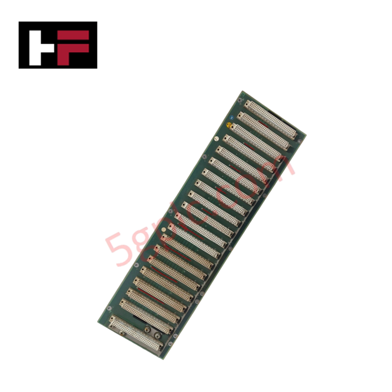
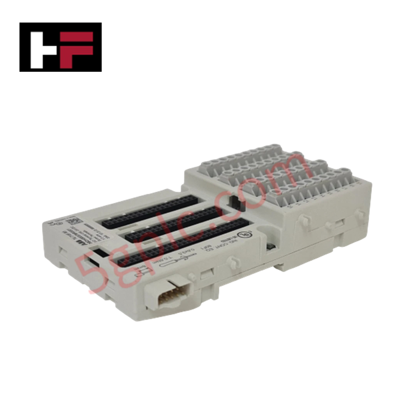
Configured for analog signal interface in control networks, the Woodward 5437-524 (5437-524 Analog Field Terminal Module) provides direct physical execution of sensor signal conditioning and wiring termination via a 37-pin connector interface.
Hardware Specifications
| Parameter | Specification |
|---|---|
| Model | 5437-524 |
| Brand | Woodward |
| Origin | USA |
| Connector Type | 37-pin |
| Terminal Type | Screw clamp |
Actuator Loop Feedback Response and Thermal Heat Sink Dissipation Profiles
The 5437-524 functions as the interface node for analog input and output loops, facilitating the conversion of field-transmitted variables into signals compatible with the central control processor. The module incorporates internal signal conditioning, including filtering and linearization, to ensure signal accuracy before processing. Thermal heat sink dissipation profiles for the module are managed through the chassis enclosure to maintain component stability during continuous operation. The hardware design supports stable actuator loop feedback response by minimizing signal attenuation and noise interference in the transmission path. By utilizing standardized screw clamp terminals, the module ensures robust electrical contact for sensitive analog variables including temperature, pressure, and flow loops.
Frequently Asked Questions
Q: Does the 37-pin connector interface require specific pin-out mapping when replacing older terminal modules?
A: Yes. Although the 37-pin connector provides standardized physical connectivity, individual pin assignments may vary between module versions. Refer to the system-specific wiring schematic to verify the interface compatibility before installation.
Q: Is this module capable of handling both passive and active analog loop signals?
A: The module is designed for general-purpose analog interface. Confirm whether the specific input channel configuration requires external loop power or if it provides excitation before connecting active field transmitters to prevent over-voltage damage.
Field Installation Guidelines
- Mounting: Secure the module within the designated cabinet space. Ensure the mounting surface provides a path to the cabinet protective earth (PE) for electromagnetic shielding.
- Wiring: Terminate field wiring using the screw clamp terminals. Tighten to the recommended torque specification to ensure long-term connection integrity under vibration.
- Shielding: Terminate all cable shields at the designated ground bar within the cabinet. Do not daisy-chain shields between loops to prevent ground loops that may introduce noise into the analog signal path.
- Inspection: Verify continuity between the field device and the module input channels before initializing control logic. Ensure all terminal connections are free of insulation residue.
Additional Information
- 100% Genuine Parts: All products are original and authentic, ensuring reliable industrial performance.
- 30-Day Refund Guarantee: Return any in-stock item within 30 days in original, unopened packaging for a full refund (excluding shipping and fees).
- 12-Month Warranty: Covers defects in materials or workmanship; excludes misuse, normal wear, or unauthorized modifications.
- Worldwide Shipping: We ship via USPS, UPS, FedEx, and DHL. Delivery times vary by country and may be subject to customs or import fees.
- Support & Contact: Technical and warranty assistance is available anytime. Contact us here: Contact.
- Purchase Guidance: Check product specifications and compatibility carefully before ordering to ensure proper application.


Tech & Buying Guide

Understanding Dry Contacts in PLC Wiring: An Industrial Automation Guide
Mastering contact switching principles is essential for reliable control panels. Field devices and PLCs interface through dry or wet contacts. This technical guide examines the mechanics of dry contacts, explores their wiring architectures, and evaluates their key advantages in industrial automation.

Ultimate Commissioning Checklist for Industrial Automation Systems: An Engineering Guide
Commissioning is the most decisive phase of an industrial automation project, transforming control hardware and software into an operational facility. Thorough testing prevents costly startup delays and builds customer confidence. This guide covers essential checklists, electrical standards, and best practices.

Redundant Automation Systems: Core Architecture, Business Value, and Technical Advantages
Unplanned downtime poses a major financial threat to process manufacturing. To prevent costly interruptions, engineers deploy redundant PLC and DCS architectures that ensure continuous operation when hardware fails. This technical guide explores redundancy principles, critical system nodes, and real-world scenarios.