


Product Details
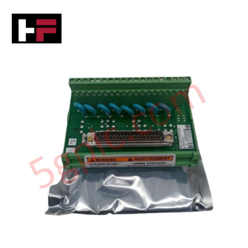
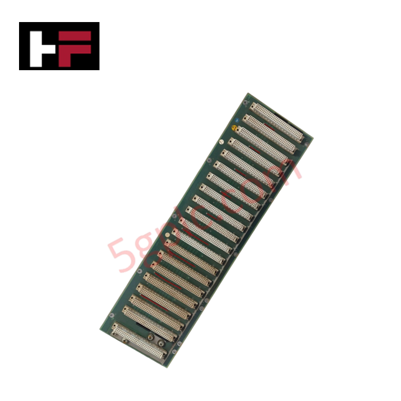
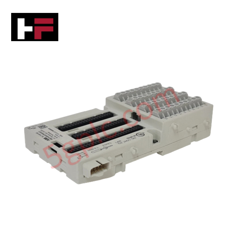
Configured for signal consolidation in TMR control architectures, the Woodward 5437-523 (Analog FTM) provides direct electrical execution of triple modular redundant output signal summation and latent fault detection within MicroNet platforms.
Hardware Specifications
| Parameter | Specification |
|---|---|
| Model | 5437-523 |
| Brand | Woodward |
| Origin | USA |
| Weight | 0.55 lbs |
| Dimensions | 6.25 in x 3.50 in x 2.75 in |
| Excitation | 2 mA |
| Input Impedance | 2.2 Mega ohm |
| Accuracy | 0.5 % |
| Isolation | 1500 VAC continuous |
| CMRR | -90 dB |
| Frequency | 3 kHz |
Actuator Loop Feedback Response and Thermal Heat Sink Dissipation Profiles
The 5437-523 FTM interfaces with MicroNet TMR kernel outputs, summing redundant signals into a single field-facing output at the terminal blocks. To maintain signal integrity and optimize actuator loop feedback response, the module provides a high input impedance of 2.2 Mega ohm and a common-mode rejection ratio (CMRR) of -90 dB. The internal circuitry utilizes field-selectable jumpers to configure latent fault detection logic, ensuring that the control system can adapt to the specific impedance and load characteristics of the interfaced circuitry. Thermal heat sink dissipation profiles for the consolidated output stages must be maintained by ensuring adequate cabinet ventilation; the 1500 VAC continuous isolation rating provides protection against ground potential differences across the signal loop.
Frequently Asked Questions
Q: How are the latent fault detection parameters configured on the 5437-523?
A: Latent fault detection logic is configured via physical jumpers located on the FTM board. Settings must be selected based on the specific load and circuitry requirements of the connected analog device to ensure accurate fault monitoring.
Q: Can this FTM be used with non-TMR MicroNet control platforms?
A: The module is designed primarily for TMR kernels where it functions to consolidate redundant signals. Use in non-TMR applications requires verification of kernel signal compatibility to ensure the summing logic does not impact single-channel signal fidelity.
Field Installation Guidelines
- Mounting: Secure the FTM to a standard DIN-rail or mounting plate within the control cabinet. Ensure sufficient clearance for the 6.25 in x 3.50 in x 2.75 in housing to allow for jumper access and cable termination.
- Jumper Configuration: Before connecting field wiring, set the internal jumpers to match the required latent fault detection logic for the intended output circuit. Consult the site-specific control schematic to determine the correct jumper position.
- Wiring: Connect the three kernel outputs to the designated FTM inputs. Ensure signal cables are shielded, with the shield terminated at the designated chassis ground point to maintain the -90 dB CMRR.
- Isolation: Verify that the 1500 VAC continuous isolation is not compromised by routing field wiring in proximity to high-voltage AC power lines. Maintain strict separation between analog signal loops and power distribution cabling.
Additional Information
- 100% Genuine Parts: All products are original and authentic, ensuring reliable industrial performance.
- 30-Day Refund Guarantee: Return any in-stock item within 30 days in original, unopened packaging for a full refund (excluding shipping and fees).
- 12-Month Warranty: Covers defects in materials or workmanship; excludes misuse, normal wear, or unauthorized modifications.
- Worldwide Shipping: We ship via USPS, UPS, FedEx, and DHL. Delivery times vary by country and may be subject to customs or import fees.
- Support & Contact: Technical and warranty assistance is available anytime. Contact us here: Contact.
- Purchase Guidance: Check product specifications and compatibility carefully before ordering to ensure proper application.


Tech & Buying Guide

Understanding Dry Contacts in PLC Wiring: An Industrial Automation Guide
Mastering contact switching principles is essential for reliable control panels. Field devices and PLCs interface through dry or wet contacts. This technical guide examines the mechanics of dry contacts, explores their wiring architectures, and evaluates their key advantages in industrial automation.

Ultimate Commissioning Checklist for Industrial Automation Systems: An Engineering Guide
Commissioning is the most decisive phase of an industrial automation project, transforming control hardware and software into an operational facility. Thorough testing prevents costly startup delays and builds customer confidence. This guide covers essential checklists, electrical standards, and best practices.

Redundant Automation Systems: Core Architecture, Business Value, and Technical Advantages
Unplanned downtime poses a major financial threat to process manufacturing. To prevent costly interruptions, engineers deploy redundant PLC and DCS architectures that ensure continuous operation when hardware fails. This technical guide explores redundancy principles, critical system nodes, and real-world scenarios.