










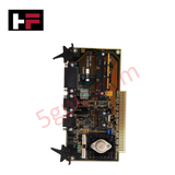
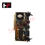
Product Details
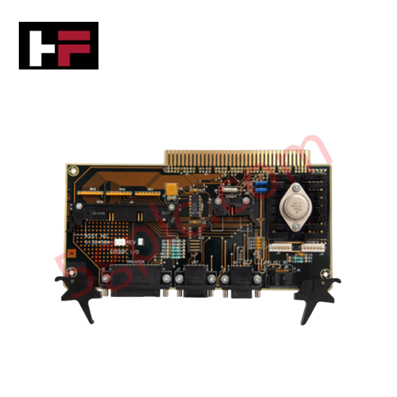
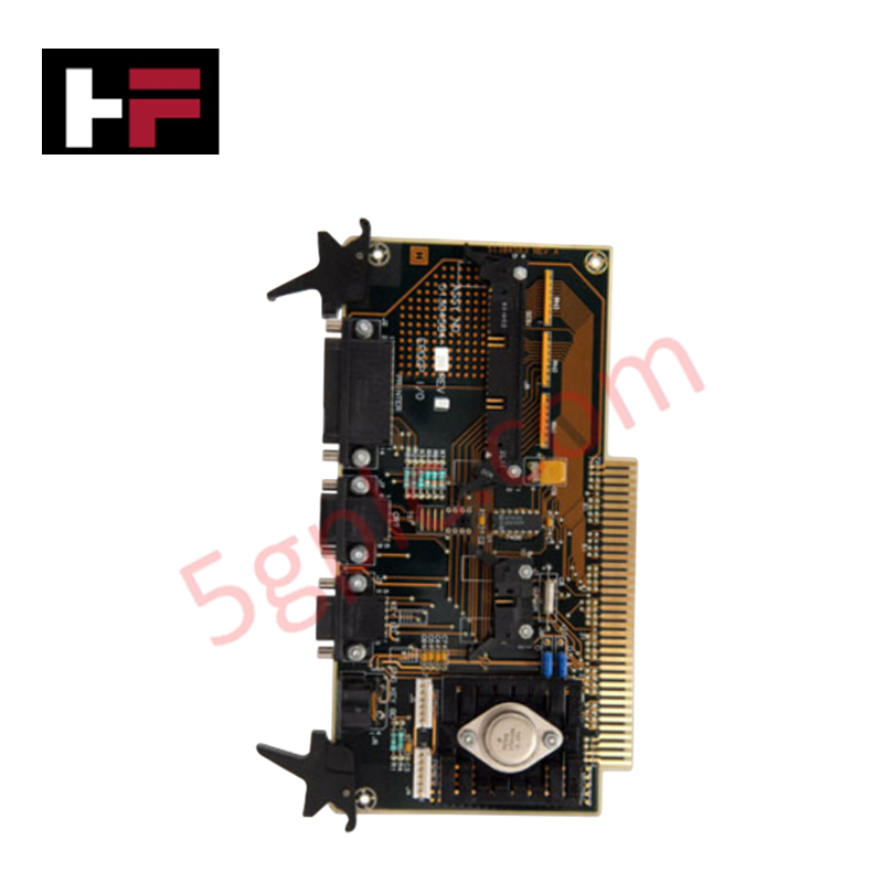
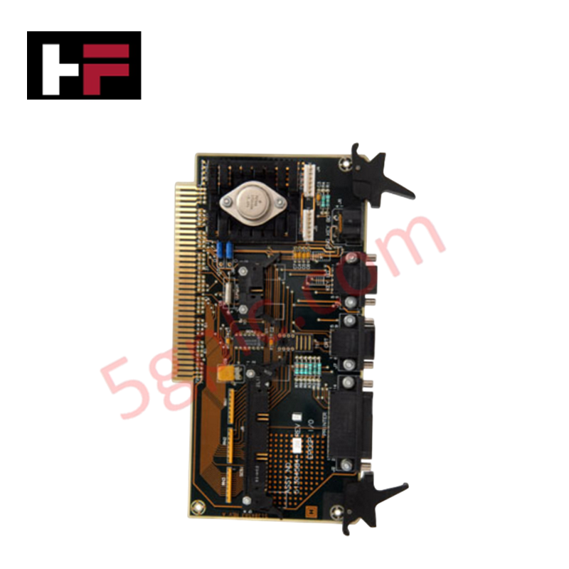
Configured for peripheral interface signal routing in Honeywell Universal Station nodes, the Honeywell 51304584-300 (51304584 EPDGP I/O Board) provides direct physical/electrical execution for video, keyboard, cursor, and drive communications across Z-Console architectures.
Hardware Specifications
| Parameter | Specification |
|---|---|
| Model | 51304584-300 |
| Brand | Honeywell |
| Origin | USA |
| Operating Temp | 0 deg C to +50 deg C |
| Power Consumption | 15 W max at backplane supply rails |
| System Compatibility | Honeywell Universal Station (EPDG and EPDG2) |
| Module Type | Enhanced Process Display Generator Peripheral (EPDGP) I/O |
| Supported Interfaces | Video, cursor control, keyboard, Zip/Bernoulli drive, parallel printer |
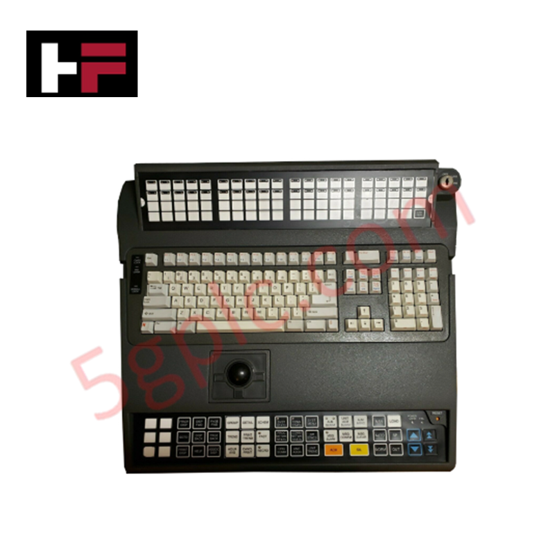
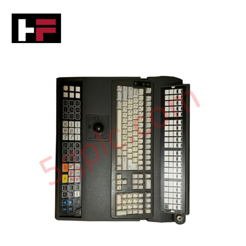
| Keyboard Compatibility | 51401952-100, 51401952-200 operator keyboards |
| Hardware Configuration | Jumper-selectable inverted sync and default background color |
4-20 mA HART Loop Protocol and Channel-to-Channel Isolation
The board isolates peripheral subsystem grounds from the main station bus to maintain signal stability across high-density operator consoles. By eliminating common-mode ground noise across video and serial peripheral links, the module prevents potential high-frequency cross-talk from interfering with adjacent cabinet signal buses carrying 4-20 mA HART loop protocol telemetry and field I/O processing paths.
Frequently Asked Questions
Q: What hardware revision level is required on the 51304584-300 for mass storage device support?
A: Rev G or higher is required to support Zip and Bernoulli drive interface communications.
Q: How is the default video display background configured on the board?
A: Onboard jumpers determine the default display state, allowing hardware selection between a grey or black background upon initialization.
Q: Is this module compatible with both EPDG and EPDG2 platform revisions?
A: Yes, the board integrates directly into Universal Station Z-Console architectures utilizing either EPDG or EPDG2 display generator assemblies.
Field Installation Guidelines
- Power down the operator workstation chassis before seating the module into the card cage slot.
- Observe static discharge safety protocols and wear a grounded wrist strap during installation.
- Verify jumper configurations for video sync polarity and default background settings prior to applying backplane power.
- Ensure terminal connections for peripheral keyboards and cursor devices are secured to avoid intermittent serial communication loss.
Additional Information
- 100% Genuine Parts: All products are original and authentic, ensuring reliable industrial performance.
- 30-Day Refund Guarantee: Return any in-stock item within 30 days in original, unopened packaging for a full refund (excluding shipping and fees).
- 12-Month Warranty: Covers defects in materials or workmanship; excludes misuse, normal wear, or unauthorized modifications.
- Worldwide Shipping: We ship via USPS, UPS, FedEx, and DHL. Delivery times vary by country and may be subject to customs or import fees.
- Support & Contact: Technical and warranty assistance is available anytime. Contact us here: Contact.
- Purchase Guidance: Check product specifications and compatibility carefully before ordering to ensure proper application.
Tech & Buying Guide

Industrial Fiber Optic Cables: Principles, Connectors, and Fusion Splicing Techniques
Modern factory automation relies heavily on fiber optic cables for high-speed industrial data transmission. Fiber optic cables transmit light pulses instead of electrical signals, eliminating electromagnetic interference (EMI) risks completely. Each optical strand consists of a high-purity glass core surrounded by a protective cladding layer. The difference in refractive index between core and cladding enables total internal reflection. Protective resin buffers, Kevlar strength members, and rugged outer jackets safeguard delicate glass cores in harsh environments. Consequently, automation engineers prefer fiber backbones for reliable noise-free communication in industrial control systems.

Comprehensive Guide to Instrumentation and Control (I&C) Design Basis
Instrumentation and Control (I&C) Design Basis serves as the foundational technical document for modern plant engineering. Project teams rely on this master specification to govern engineering deliverables across front-end engineering design (FEED) and detailed execution phases. A well-constructed I&C design basis ensures seamless integration among field instrumentation, safety systems, and main control systems. Furthermore, establishing clear technical standards early mitigates execution risks and prevents costly re-engineering during plant commissioning.

The Shift to Flexible IO Modules in Modern Industrial Automation
Traditional control systems rely on dedicated Input Output (IO) cards for industrial automation. Each conventional module processes a single signal type, such as Digital Input (DI), Digital Output (DO), Analog Input (AI), or Analog Output (AO). A standard 16-channel card accepts only one specific channel type across all ports. This inflexible hardware design often creates severe engineering bottlenecks during project execution. Engineers frequently must install entirely new cards to accommodate a single extra sensor. Consequently, late design changes increase control cabinet space requirements and drive up project costs.