










Product Details
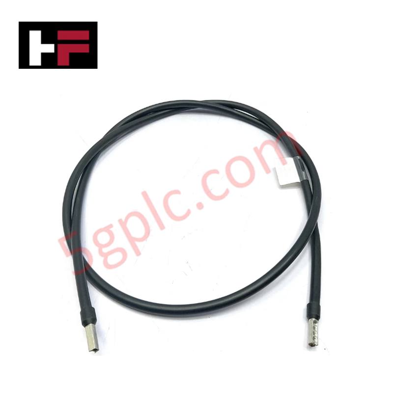
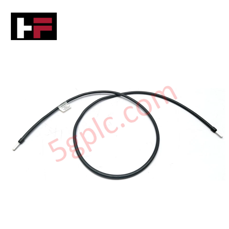
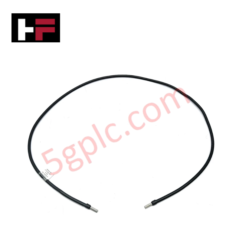
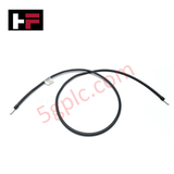
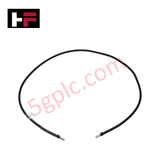
The Honeywell 51204037-002, also cataloged as the 51204037 Cable, operates as a dedicated hardware component for physical point-to-point signal interconnection within Honeywell distributed control system platforms. Configured for digital signal execution and Modbus RTU protocol interface routing, the assembly maintains serial data continuity and handles 24 V DC supply loops over a 2 meter length boundary.
Hardware Specifications
| Parameter | Specification |
|---|---|
| Model | 51204037-002 |
| Brand | Honeywell |
| Origin | USA |
| Dimensions | 2 meters (Length) |
| Operating Temp | -20 to +60 deg C |
| Power Consumption | 5 W |
| Communication Protocol | Modbus RTU |
| Output Type | Digital output |
| Housing Material | Stainless steel |
| Mounting Type | DIN rail |
| Operating Voltage | 24 V DC |
| Storage Temperature | -40 to +85 deg C |
Honeywell DCS Channel-to-Channel Isolation Parameters
The hardware architecture uses high-grade internal dielectric barriers paired with an external stainless steel shielding matrix to meet standard channel-to-channel isolation criteria on adjacent I/O modules. This mechanical baseline suppresses high-frequency inductive cross-talk and blocks transient common-mode voltage fluctuations across the serial path, preserving the transmission integrity of the Modbus RTU and 4-20 mA HART loop protocol layers against intense electromagnetic interference inside the terminal cabinet enclosure.
Frequently Asked Questions
Q: Can this industrial communication cable be detached while the associated 24 V DC digital output loops are energized?
A: No, live extraction can break inductive loop boundaries and induce localized arcing; standard technical practices require the specific channel power supply to be isolated prior to mechanical unlatching.
Q: How does the integrated 5 W power consumption parameter manifest in this passive cable assembly?
A: The 5 W rating indicates the maximum thermal dissipation and resistive distribution capacity allowed across the internal conductors when routing digital output currents under full electrical load conditions.
Field Installation Guidelines
- Clip the integrated stainless steel termination housing securely onto the designated DIN rail segment to ground the structural assembly footprint.
- Route the 2 meter cable length through dedicated low-voltage wire trays, ensuring complete isolation from adjacent AC power lines or heavy motor drive paths.
- Observe standard minimum bending radius parameters during installation to prevent conductor elongation or fractures inside the shielding envelope.
- Verify all physical pin connections seat completely into the receiver module socket, ensuring the locking tabs are engaged to withstand industrial ambient vibrations.
Additional Information
- 100% Genuine Parts: All products are original and authentic, ensuring reliable industrial performance.
- 30-Day Refund Guarantee: Return any in-stock item within 30 days in original, unopened packaging for a full refund (excluding shipping and fees).
- 12-Month Warranty: Covers defects in materials or workmanship; excludes misuse, normal wear, or unauthorized modifications.
- Worldwide Shipping: We ship via USPS, UPS, FedEx, and DHL. Delivery times vary by country and may be subject to customs or import fees.
- Support & Contact: Technical and warranty assistance is available anytime. Contact us here: Contact.
- Purchase Guidance: Check product specifications and compatibility carefully before ordering to ensure proper application.


Tech & Buying Guide
Demystifying Programmable Logic Controllers: Comprehensive Guide to PLC Classification and Selection in Industrial Automation
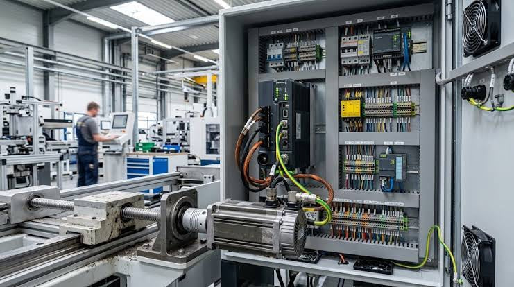
Modern industrial automation heavily relies on Programmable Logic Controllers (PLCs) to drive factory floor efficiency. Over my 15 years as an industrial automation expert working with DCS, TSI, and control systems, I have seen PLCs evolve into the central nervous system of modern manufacturing. Selecting the right controller requires a deep understanding of PLC types based on physical size, hardware architecture, and power supply configurations.
Comprehensive Guide to PLC Types in Modern Industrial Automation
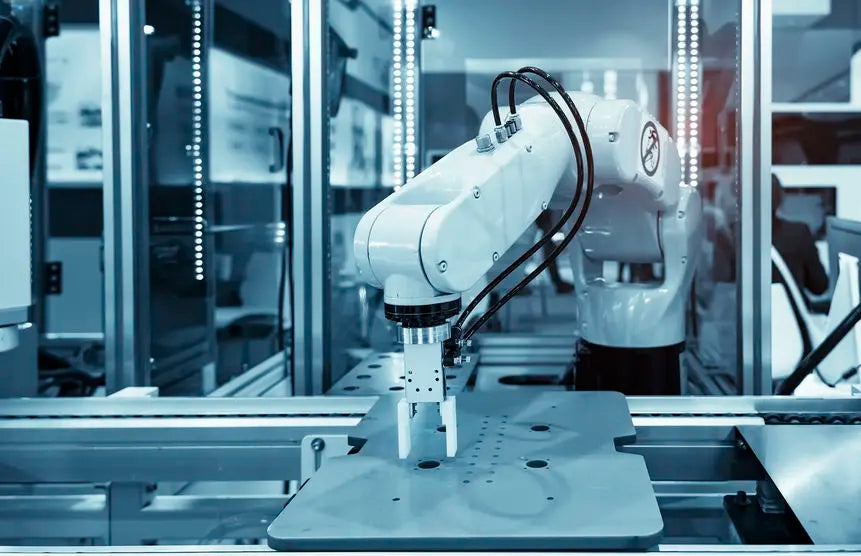
Modern industrial automation relies on programmable logic controllers to govern critical factory operations. System integrators classify PLCs based on scale, hardware architecture, and power supply design. Understanding these core categories enables automation engineers to select the right control system architecture. Consequently, proper hardware selection optimizes performance while minimizing long-term operational costs.

Demystifying the DDE Protocol in Legacy Industrial Automation Systems
Modern control systems rely heavily on seamless interprocess communication to exchange operational data between software programs. Microsoft first introduced the Dynamic Data Exchange (DDE) protocol in 1987 to enable real-time data sharing. In factory automation, DDE served as an early bridge between control software and Windows desktop applications. Therefore, understanding DDE mechanics provides crucial insights into how legacy industrial networks established software-level connectivity.