


Product Details
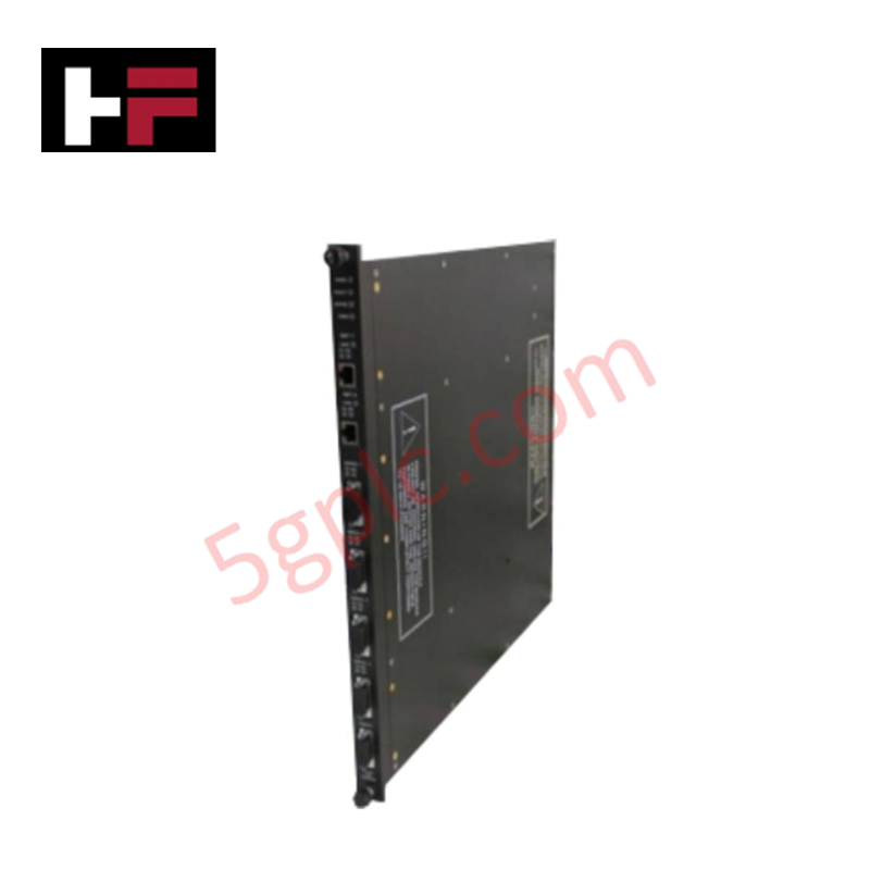
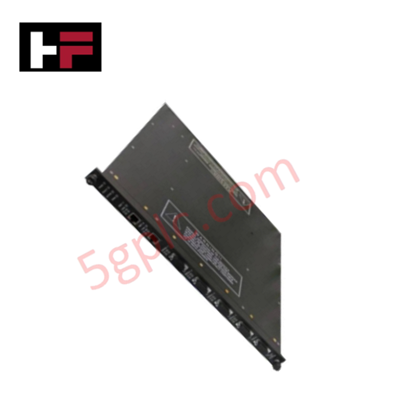
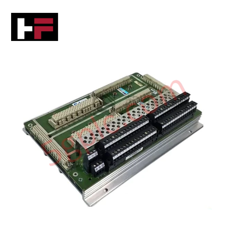
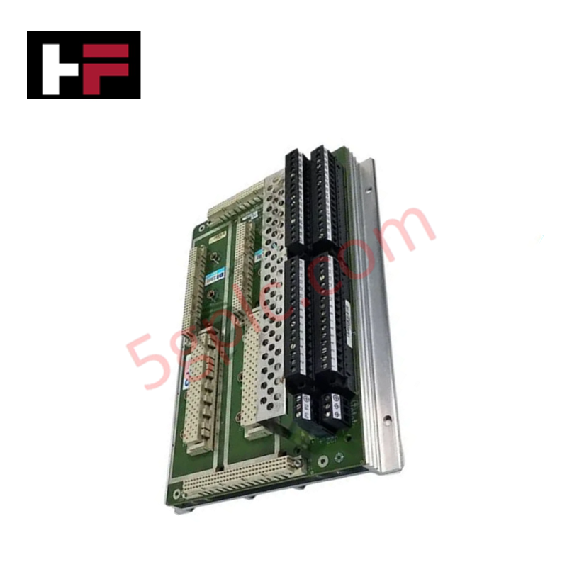
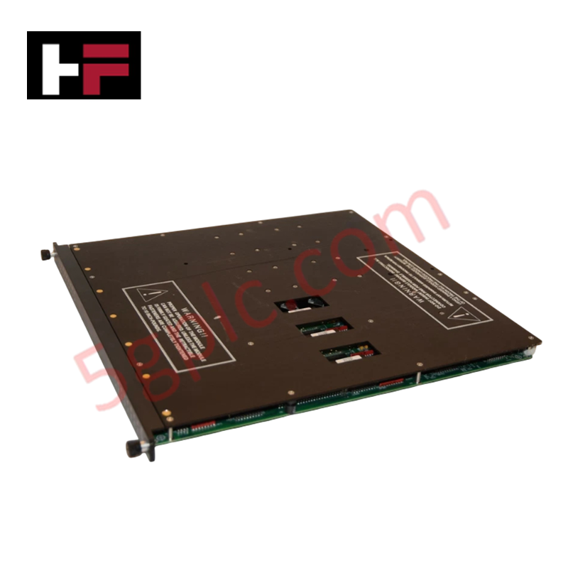
Configured for high-density digital signal control in Tricon safety system platforms, the Triconex 3625A (3625A Digital Output Module) provides direct physical/electrical execution of safety-critical output switching via a 32-point commoned interface.
Hardware Specifications
| Parameter | Specification |
|---|---|
| Model | 3625A |
| Brand | Triconex |
| Origin | Refer to Original Equipment Documentation |
| Weight | Refer to Technical Manual |
| Dimensions | Standard Tricon module form factor |
| Operating Temp | Industrial standard range |
| Power Consumption | < 13 W |
| Output Points | 32, commoned |
| Voltage Rating | 24 VDC (16-32 VDC range) |
| Isolation | 1,500 VDC |
Triple Modular Redundancy (TMR) Architectural Integration
The Triconex 3625A is engineered for operation within a TMR 2oo3 architecture, ensuring that digital output state execution is governed by a majority-voting mechanism across three independent processor paths. This configuration provides the necessary fault tolerance required for SIL3 certification compliance. The module incorporates 1,500 VDC point isolation to suppress common-mode electrical noise and protect the system backplane from field-side transients. In the event of an internal diagnostic failure or a detected discrepancy between redundant channels, the module initiates fail-safe state execution to ensure that connected valves, solenoids, or alarms revert to a predefined safe state.
Frequently Asked Questions
Q: Does the 3625A module support hot-swapping during active system operation?
A: Yes, the 3625A supports hot-swapping within the Tricon chassis. When a replacement module is inserted, it performs an internal power-on self-test and synchronizes output states with the existing redundant modules before transitioning to an operational state.
Q: Are the output points supervised or non-supervised?
A: The 3625A is configured for supervised/non-supervised digital output operation. Refer to the system software configuration and application logic to verify the specific supervision state of each output point.
Field Installation Guidelines
- Ensure the chassis slot is properly prepared and free of debris before inserting the 3625A module.
- Align the module with the chassis guide rails and push firmly to ensure full engagement with the backplane connector.
- Tighten the captive retaining screws on the front panel to provide mechanical stability and ensure electrical grounding of the module chassis.
- Verify that field wiring connected to the 32-point commoned interface is properly insulated and routed to prevent short circuits.
- Use shielded cabling where necessary to maintain the integrity of the 24 VDC control loops and minimize electromagnetic interference from high-current field devices.
Additional Information
- 100% Genuine Parts: All products are original and authentic, ensuring reliable industrial performance.
- 30-Day Refund Guarantee: Return any in-stock item within 30 days in original, unopened packaging for a full refund (excluding shipping and fees).
- 12-Month Warranty: Covers defects in materials or workmanship; excludes misuse, normal wear, or unauthorized modifications.
- Worldwide Shipping: We ship via USPS, UPS, FedEx, and DHL. Delivery times vary by country and may be subject to customs or import fees.
- Support & Contact: Technical and warranty assistance is available anytime. Contact us here: Contact.
- Purchase Guidance: Check product specifications and compatibility carefully before ordering to ensure proper application.


Tech & Buying Guide

Strategic Selection: Choosing the Right SCADA Software for Your PLC Project
In industrial automation, the SCADA (Supervisory Control and Data Acquisition) system acts as the bridge between raw machine data and actionable human intelligence. Selecting the incorrect software platform can lead to integration bottlenecks, scalability issues, and excessive long-term maintenance costs. As an automation consultant with 15 years of experience, I have guided many projects through the selection process. Below are the essential criteria for choosing a platform that ensures both performance and longevity.

Ensuring Operational Continuity: The Strategic Value of Redundant Automation Systems
In modern industrial landscapes, unplanned downtime is the ultimate adversary. For sectors relying on complex PLC and DCS architectures, a single hardware failure can trigger catastrophic production losses. Therefore, implementing redundant automation systems is no longer a luxury; it is a fundamental requirement for mission-critical operations. In this article, I analyze why redundancy remains the backbone of reliable industrial infrastructure.

Selecting the Right Cables for Industrial Automation: A Comprehensive Guide
Selecting the appropriate cabling infrastructure is critical for the success of any industrial automation project. Improper cable selection often leads to signal degradation, system instability, and costly downtime. As an automation engineer, I frequently see projects compromised by poor cabling choices in harsh industrial environments. This guide simplifies the complex landscape of cabling to help you make informed decisions for your PLC, DCS, and control systems.