


Product Details
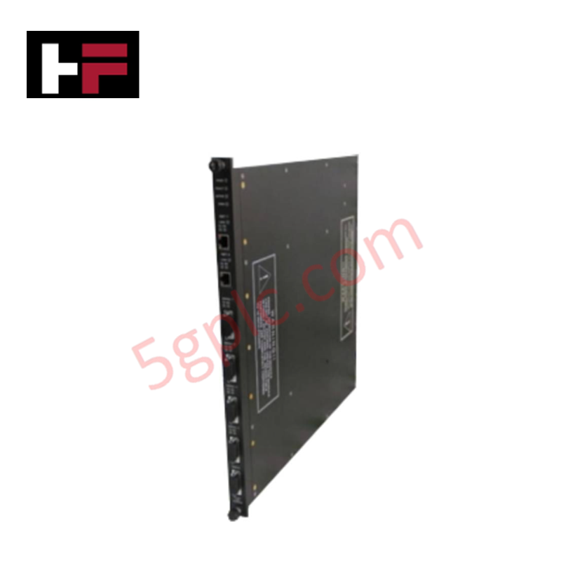
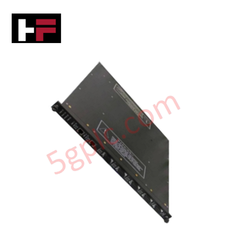
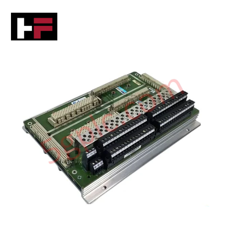
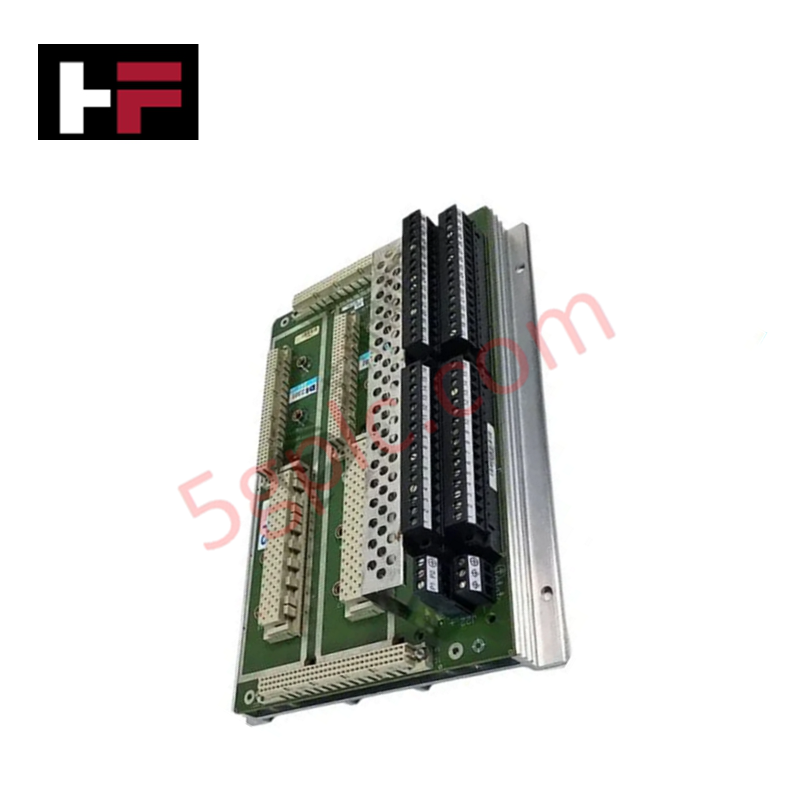
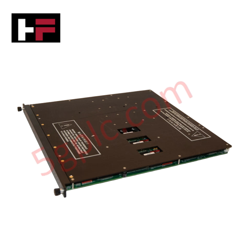
Configured for high-density signal acquisition in Tricon safety system platforms, the Triconex 3501E (3501E Digital Input Module) provides direct physical/electrical execution of 32-channel 115 VAC/VDC digital input monitoring.
Hardware Specifications
| Parameter | Specification |
|---|---|
| Model | 3501E |
| Brand | Triconex |
| Dimensions | Standard Tricon module form factor |
| Operating Temp | Industrial standard range |
| Power Consumption | 2.9 W |
| Input Points | 32 points |
| Voltage Range | 90-155 VAC/VDC |
| Isolation | 1500 VDC to 2500 VDC |
Triple Modular Redundancy (TMR) Architectural Integrity
The Triconex 3501E operates within a TMR 2oo3 architecture, ensuring that digital input states are processed via three independent channels with real-time majority voting. This mechanism eliminates single-point failures and ensures system state integrity. The module provides galvanic isolation ranging from 1500 VDC to 2500 VDC between the field input terminals and the backplane, protecting the internal logic solver from electrical transients and common-mode noise. To satisfy SIL3 certification requirements, the module supports fail-safe state execution; in the event of an internal diagnostic failure, the module isolates the faulty channel and reports a diagnostic fault to the main processor to prevent erroneous data transmission.
Frequently Asked Questions
Q: Does the 3501E support hot-swapping during active system operation?
A: Yes, the 3501E is designed for hot-swapping within an energized Tricon chassis. Upon installation, the module performs a power-on self-test and synchronizes with the redundant processor set before resuming active signal scanning.
Q: Can the 3501E handle both AC and DC input signals simultaneously?
A: The module is rated for 115 VAC/VDC input signals within the 90-155 VAC/VDC range. While the hardware supports both voltage types, all inputs within a single module must adhere to the configured field-side voltage requirements to maintain signal detection accuracy and prevent potential input impedance mismatches.
Field Installation Guidelines
- Ensure the system chassis is in a state permitting module replacement before insertion.
- Align the 3501E with the chassis guide rails and firmly seat the module to engage the backplane connector.
- Tighten the front-panel captive screws to establish a secure ground connection to the chassis.
- Route field wiring according to local electrical codes, ensuring proper separation between the 115 VAC/VDC input signals and low-voltage control loops to prevent induced interference.
- Terminate input signal cable shields at the cabinet ground bus to ensure the effectiveness of the galvanic isolation barrier.
Additional Information
- 100% Genuine Parts: All products are original and authentic, ensuring reliable industrial performance.
- 30-Day Refund Guarantee: Return any in-stock item within 30 days in original, unopened packaging for a full refund (excluding shipping and fees).
- 12-Month Warranty: Covers defects in materials or workmanship; excludes misuse, normal wear, or unauthorized modifications.
- Worldwide Shipping: We ship via USPS, UPS, FedEx, and DHL. Delivery times vary by country and may be subject to customs or import fees.
- Support & Contact: Technical and warranty assistance is available anytime. Contact us here: Contact.
- Purchase Guidance: Check product specifications and compatibility carefully before ordering to ensure proper application.


Tech & Buying Guide

Strategic Selection: Choosing the Right SCADA Software for Your PLC Project
In industrial automation, the SCADA (Supervisory Control and Data Acquisition) system acts as the bridge between raw machine data and actionable human intelligence. Selecting the incorrect software platform can lead to integration bottlenecks, scalability issues, and excessive long-term maintenance costs. As an automation consultant with 15 years of experience, I have guided many projects through the selection process. Below are the essential criteria for choosing a platform that ensures both performance and longevity.

Ensuring Operational Continuity: The Strategic Value of Redundant Automation Systems
In modern industrial landscapes, unplanned downtime is the ultimate adversary. For sectors relying on complex PLC and DCS architectures, a single hardware failure can trigger catastrophic production losses. Therefore, implementing redundant automation systems is no longer a luxury; it is a fundamental requirement for mission-critical operations. In this article, I analyze why redundancy remains the backbone of reliable industrial infrastructure.

Selecting the Right Cables for Industrial Automation: A Comprehensive Guide
Selecting the appropriate cabling infrastructure is critical for the success of any industrial automation project. Improper cable selection often leads to signal degradation, system instability, and costly downtime. As an automation engineer, I frequently see projects compromised by poor cabling choices in harsh industrial environments. This guide simplifies the complex landscape of cabling to help you make informed decisions for your PLC, DCS, and control systems.