
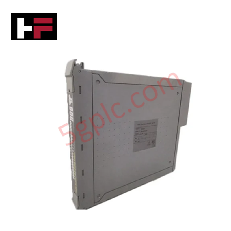
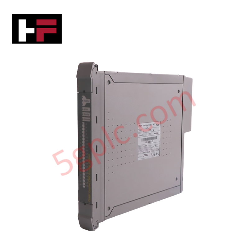
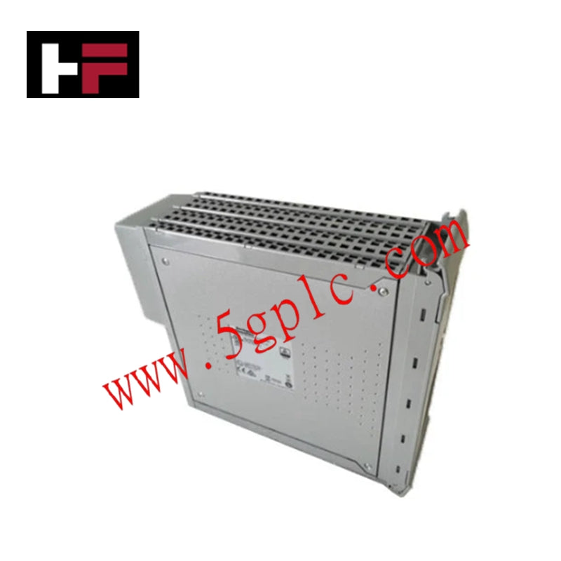
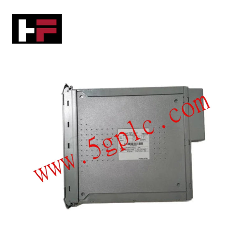


Product Details
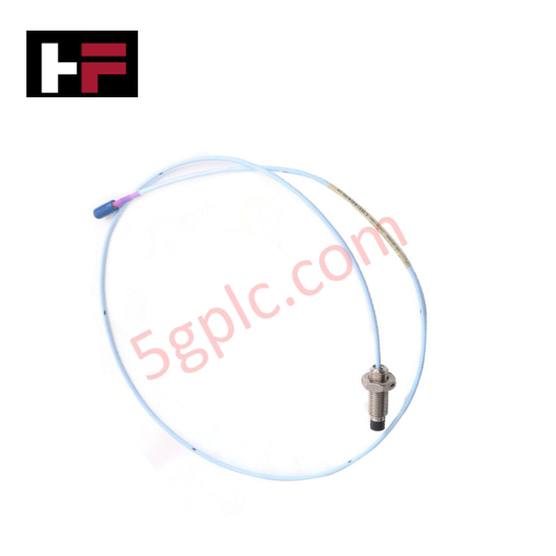
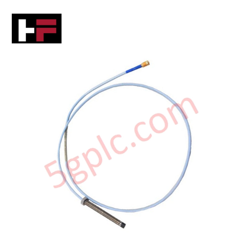
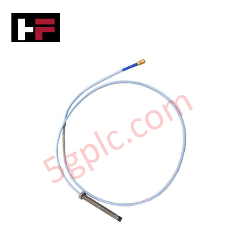
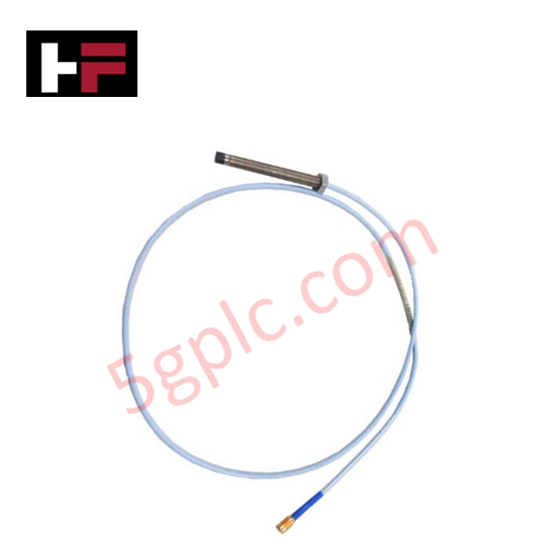
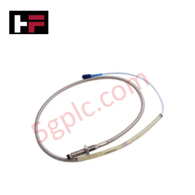
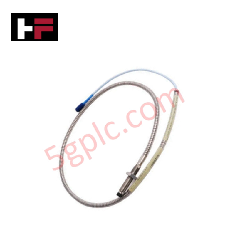
The 330104-05-13-10-02-00 is an armored 8 mm proximity probe from the 3300 XL transducer platform, designed for non-contact vibration and position monitoring in industrial machinery. This eddy-current sensor delivers precise shaft displacement measurements while utilizing an M10 x 1 metric thread profile and integrated stainless steel cable armor.
Suffix Breakdown & Configuration
The model code establishes a specific mechanical and electrical configuration within the 3300 XL series. The base designation 330104 denotes an 8 mm proximity probe featuring an M10 x 1 thread with protective stainless steel armor.
The configuration options define precise physical attributes: an unthreaded length of 50 mm (code 05), an overall case length of 130 mm (code 13), and a total cable length of 1.0 meter / 3.3 feet (code 10). It terminates in a miniature ClickLoc coaxial connector (code 02) and includes no hazardous-area agency approvals (code 00).
Hardware Specifications
| Parameter | Specification |
|---|---|
| Model | 330104-05-13-10-02-00 |
| Brand | Bently Nevada |
| Product Type | 3300 XL 8 mm Proximity Probe |
| Thread Size | M10 x 1 with armor |
| Unthreaded Length | 50 mm (Option 05) |
| Overall Case Length | 130 mm (Option 13) |
| Total Cable Length | 1.0 meter (3.3 feet) |
| Connector Type | Miniature ClickLoc coaxial connector |
| Agency Approval | Not required (Option 00) |
| Probe Tip Material | Polyphenylene sulfide (PPS) |
| Probe Case Material | AISI 303 or 304 stainless steel (SST) |
| Linear Range | 2 mm (80 mils) from 0.25 mm to 2.3 mm |
| Output Voltage Range | Approximately -1 to -17 Vdc across linear range |
| Nominal DC Resistance | 7.59 plus or minus 0.50 ohms |
| Weight | 323 g/m (11.4 oz) |
Field Installation Guidelines
Do not cut or modify the armored probe cable, as factory termination preserves the precise electrical length and impedance required for system calibration. Maintain the manufacturer-specified maximum probe case torque of 33.9 N-m (300 in-lbf), with a recommended installation torque of 11.2 N-m (100 in-lbf).
Route signal cables away from high-frequency switching conductors to minimize induced electrical noise, and ensure the ClickLoc connector is fully seated before system startup.
Frequently Asked Questions
Q: Does the 330104-05-13-10-02-00 probe include hazardous area certifications?
A: No. Option 00 indicates that agency approvals are not required or included with this specific configuration.
Q: What is the recommended installation torque for this probe model?
A: The recommended installation torque is 11.2 N-m (100 in-lbf), with a maximum allowable case torque of 33.9 N-m (300 in-lbf).
Q: What are the unthreaded and overall case length dimensions?
A: It features a 50 mm unthreaded length (option 05) and a 130 mm overall case length (option 13) designed for standard metric housings.
Additional Information
- 100% Genuine Parts: All products are original and authentic, ensuring reliable industrial performance.
- 30-Day Refund Guarantee: Return any in-stock item within 30 days in original, unopened packaging for a full refund (excluding shipping and fees).
- 12-Month Warranty: Covers defects in materials or workmanship; excludes misuse, normal wear, or unauthorized modifications.
- Worldwide Shipping: We ship via USPS, UPS, FedEx, and DHL. Delivery times vary by country and may be subject to customs or import fees.
- Support & Contact: Technical and warranty assistance is available anytime. Contact us here: Contact.
- Purchase Guidance: Check product specifications and compatibility carefully before ordering to ensure proper application.



Tech & Buying Guide

Essential Technical Glossary of Electrical Grounding and Bonding in Industrial Automation
In industrial automation, precise grounding terminology prevents catastrophic equipment failure. Therefore, engineers must master the foundational concepts of earth and ground. Earth represents the conductive mass of the planet, providing a zero-potential reference point. Ground defines a deliberate or accidental connection between an electrical circuit and earth. Furthermore, an effectively grounded system maintains low impedance to prevent hazardous voltage buildups during electrical faults.
Essential Guide to Grounding Electronic Equipment in Industrial Automation
Industrial automation systems require robust grounding for personal safety and fault clearance. Safety grounding minimizes touch potential across exposed metallic enclosures. It ensures rapid clearance of fuses during electrical faults. However, electronic equipment introduces unique performance requirements. Solid-state devices operate at high speeds. Therefore, they exhibit extreme sensitivity to minor voltage transients. Facility engineers must balance electrical safety with operational signal integrity.

Engineering Guide to Selecting Electrical Earthing and Grounding Components in Industrial Automation
The overall reliability of any industrial automation network relies heavily on its grounding components. Control systems, PLCs, and distributed control systems (DCS) require rigorous earthing to mitigate electrical noise and faults. Engineers must select each component with extreme care. Furthermore, proper interconnection methods dictate whether a facility operates safely or suffers from chronic signal disruption.