










Product Details
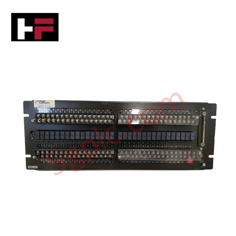
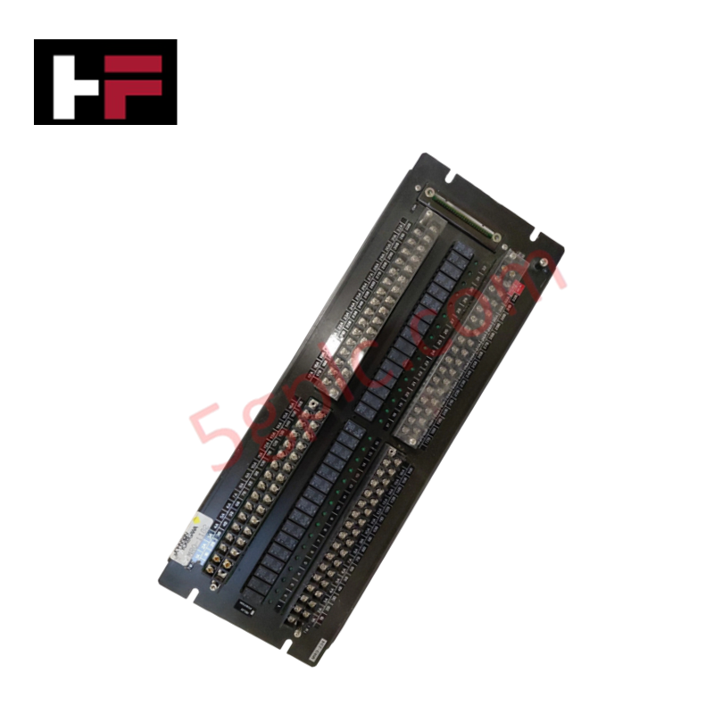
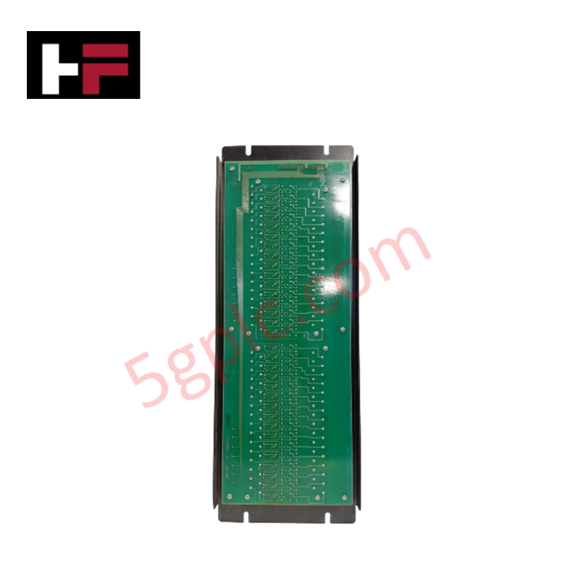
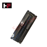
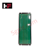
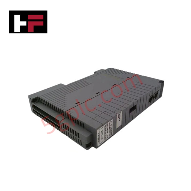
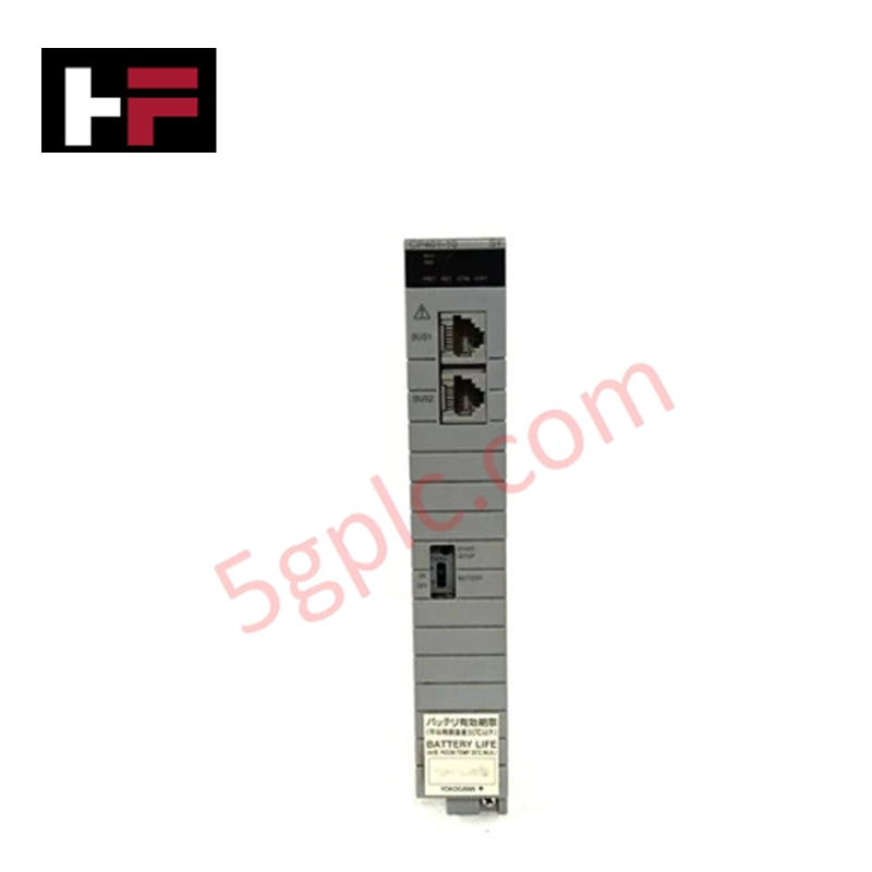
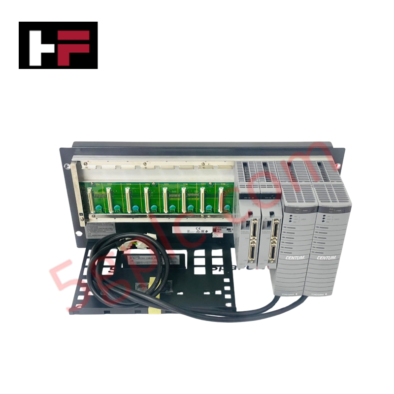
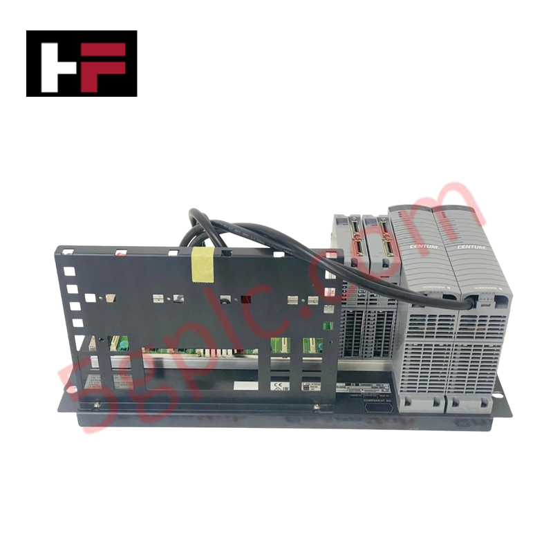
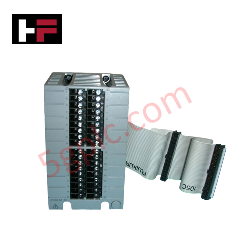
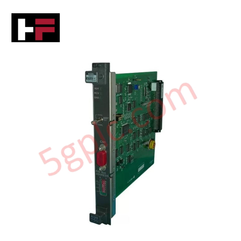
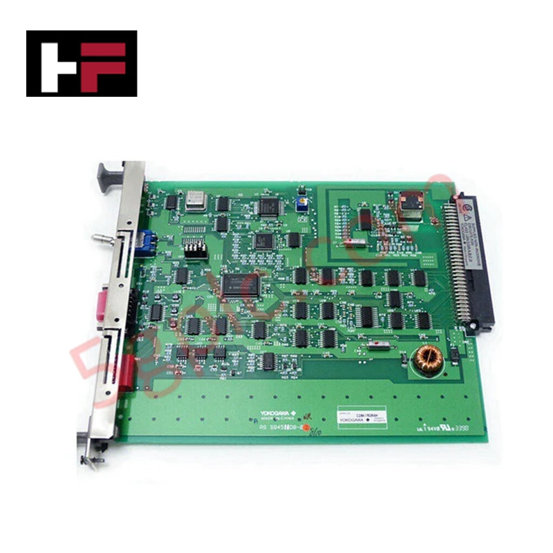
The Yokogawa MRO-234*A, also cataloged as the MRO-234 SPDT Relay Output Module, operates as a dedicated hardware component for galvanic isolation and digital contact switching execution within Yokogawa DCS control networks. It accepts low-voltage control signals to actuate Single Pole Double Throw (SPDT) electromechanical contacts, interfacing logic controllers directly with field actuators, solenoids, and alarm indicators across discrete control loops.
Suffix Breakdown & Model Matrix
| Parameter | Specification |
|---|---|
| MRO-234 | Base module series for multi-channel SPDT relay output processing |
| *A | Style code Revision A denoting standard board layout and terminal arrangement |
Hardware Specifications
| Parameter | Specification |
|---|---|
| Model | MRO-234*A |
| Brand | Yokogawa |
| Origin | Japan |
| Weight | 0.5 kg |
| Dimensions | 99 x 100 x 40 mm |
| Operating Temp | -20 deg C to 60 deg C |
| Power Consumption | 2.5 W nominal (coil energized state) |
| Contact Configuration | SPDT (Form C) electromechanical relay contacts |
| Nominal Coil Voltage | 24 VDC |
| Maximum Switching Voltage | 250 VAC / 125 VDC |
| Maximum Continuous Current | 2 A per contact channel |
| Galvanic Isolation | 2000 VAC between coil circuit and contact terminals |
Channel-to-Channel Isolation and Inductive Load Suppression
The MRO-234*A relay board delivers complete galvanic isolation between sensitive internal DCS control electronics and high-voltage field loads. Each output channel utilizes dedicated optocouplers and mechanical relay armatures to prevent inductive voltage spikes, electrical fast transients (EFT), and ground loops from propagating back to the main system backplane. Built-in flyback diodes across the 24 VDC coil circuits dissipate counter-electromotive force (counter-EMF), stabilizing DC power rails during rapid contact switching cycles.
Frequently Asked Questions
Q: What is the recommended contact protection when switching highly inductive DC loads with the MRO-234*A?
A: Connect a free-wheeling flyback diode in parallel with inductive DC loads (such as solenoid valves or contactor coils) to suppress voltage transients and prevent contact erosion or arc-welding.
Q: Does the MRO-234*A module support hot-swapping under live power conditions?
A: Removal or insertion of the module should only occur after de-energizing field power to the relay contacts to prevent accidental switching states or terminal arcing during contact mating.
Q: What is the physical breakdown voltage limit between channels?
A: The internal barrier provides continuous dielectric isolation up to 2000 VAC for 1 minute between control logic inputs and field contact outputs.
Field Installation Guidelines
- Physical Mounting: Secure the module onto DIN rail or enclosure mounting plates using the integrated retention clips. Maintain at least 50 mm clearance above and below the module for adequate thermal convection.
- Wiring and Strain Relief: Use AWG 14 to AWG 22 stranded copper wire for field contact connections. Ensure terminal block screws are torqued to 0.5 N-m to prevent high-resistance contact points.
- Cable Separation: Route 24 VDC coil supply lines and high-voltage AC load cables through separate wire ducts to prevent crosstalk and capacitive noise coupling.
- Grounding: Bond the panel DIN rail or mounting chassis directly to the main functional earth (FE) bus bar using a low-impedance grounding strap.
Additional Information
- 100% Genuine Parts: All products are original and authentic, ensuring reliable industrial performance.
- 30-Day Refund Guarantee: Return any in-stock item within 30 days in original, unopened packaging for a full refund (excluding shipping and fees).
- 12-Month Warranty: Covers defects in materials or workmanship; excludes misuse, normal wear, or unauthorized modifications.
- Worldwide Shipping: We ship via USPS, UPS, FedEx, and DHL. Delivery times vary by country and may be subject to customs or import fees.
- Support & Contact: Technical and warranty assistance is available anytime. Contact us here: Contact.
- Purchase Guidance: Check product specifications and compatibility carefully before ordering to ensure proper application.


Tech & Buying Guide

Industrial Networking Essentials: Demystifying Hubs, Switches, and Routers in Control Systems
Industrial automation relies heavily on robust networking infrastructure to connect programmable logic controllers (PLCs), distributed control systems (DCS), and human-machine interfaces (HMIs). Modern factory automation environments generate vast amounts of real-time operational data across deterministic networks. Understanding the structural differences between hubs, switches, and routers ensures optimal traffic segmentation, minimizes latency, and maintains high network availability.

Safety Relays in Industrial Automation: Fundamentals, Design Standards, and Fail-Safe Architecture
Safety relays form the bedrock of functional safety in modern factory automation, preventing catastrophic equipment failure and protecting plant personnel. While standard electromechanical relays handle basic load switching, they lack the redundant diagnostics required for high-risk industrial environments. Modern industrial automation platforms—including programmable logic controllers (PLCs) and distributed control systems (DCS)—rely on specialized safety relays to monitor field devices and isolate hazards instantly.

Voice-Activated Industrial Automation: Integrating Speech Control into PLC and DCS Architectures
Industrial automation integrates speech recognition, IIoT protocols, and NLP with PLCs and DCS to streamline operations. By leveraging advanced edge computing, engineers enable real-time, hands-free control—allowing personnel to manage smart factory processes safely away from hazardous equipment.