


Product Details
Product Overview
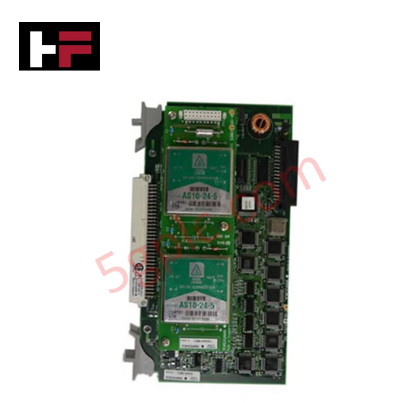
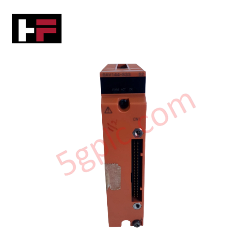
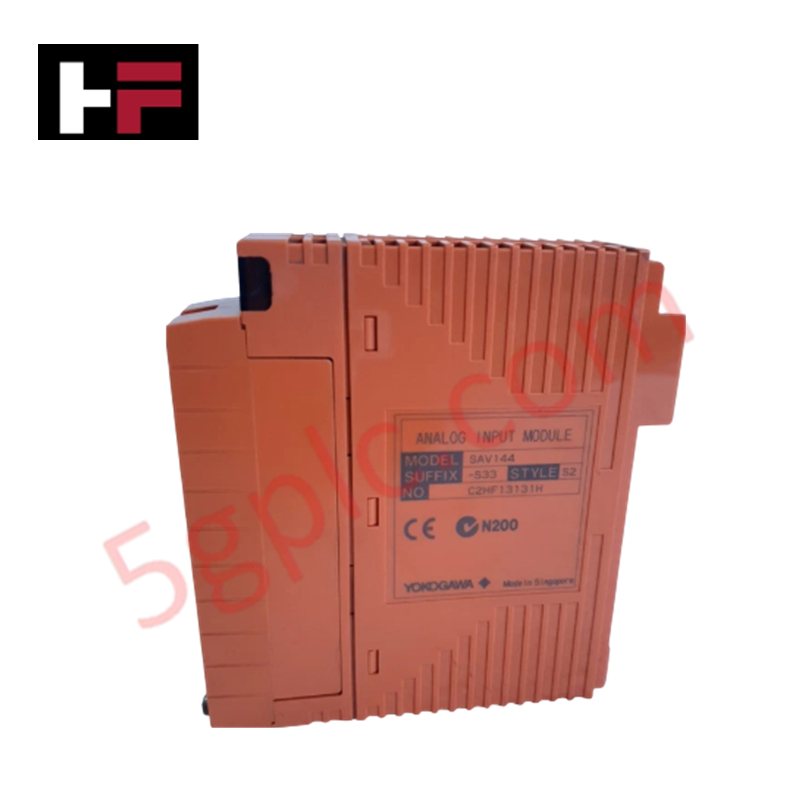
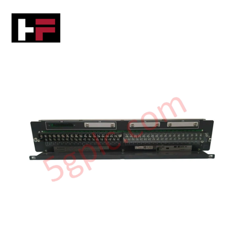
The Yokogawa AMM42 is a specialized multiplexer input module engineered for high-reliability Field Control Stations (FCS) within the CENTUM CS and VP distributed control systems. It is specifically designed to support a fully redundant configuration, effectively eliminating single points of failure in critical process automation environments. By utilizing Yokogawa's robust "Pair and Spare" technology, this module ensures that the control station maintains operational continuity even during hardware faults, making it an essential component for Safety Instrumented Systems (SIS) where TÜV certification and system availability are paramount.
Technical Specifications
The AMM42 is built to interface directly with field transmitters while managing power and signal integrity within a redundant architecture.
| Parameter | Specification |
|---|---|
| Product Type | Multiplexer Input Module |
| Model Number | AMM42 |
| Application | Field Control Station (FCS) Redundant Configuration |
| Transmitter Power Supply | 23.5 to 24.5 V DC |
| Output Power Limit | 60 mA or less |
| Input Resistance | 250 Ω (Standard) / 70 Ω (With Barrier) |
| Signal Isolation | Non-isolated (System-to-Field and Channel-to-Channel) |
| Redundancy | Supports "Pair and Spare" Architecture |
| Certification | TÜV Rheinland (SIS Applications) |
Model Code Interpretation
Understanding the suffix logic is vital for ensuring the correct hardware revision and compatibility with your carrier system.
Part Number: AMM42-S4
AMM42-AXX
-
A (Suffix -S4): This suffix typically designates the specific hardware revision and connector interface type.
-
S: Often indicates a "Spring-clamp" or specific terminal block style compatible with the AMN series carrier boxes (e.g., AMN34).
-
4: Denotes the specific series or revision level, ensuring compatibility with the redundant bus architecture of the FCS.
Note: Always verify the suffix against your system's I/O allocation sheet to ensure it matches the carrier type and redundancy requirements.
Installation and Wiring Guidelines
Proper installation of the AMM42 is critical to maintaining the integrity of the redundant system.
-
Redundancy Configuration: The AMM42 is designed for redundant setups. Ensure that the module is installed in the correct slots as defined by the system architecture (typically involving paired modules). Incorrect slotting can prevent the "Pair and Spare" logic from functioning.
-
Power Supply Limits: The module provides a transmitter power supply of 23.5 to 24.5 V DC. Do not exceed the output power limit of 60 mA per channel to avoid damaging the internal power regulation circuitry.
-
Input Resistance Configuration:
-
The standard input resistance is 250 Ω.
-
If your system utilizes safety barriers, you may need to modify the resistance to 70 Ω. This is typically done via jumpers or switches on the module (refer to the hardware manual).
-
Isolation Awareness: Be aware that there is no electrical isolation between the system and the field, nor between individual channels. Proper grounding of the field wiring and the control system is essential to prevent ground loops and signal noise.
-
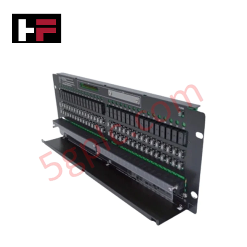
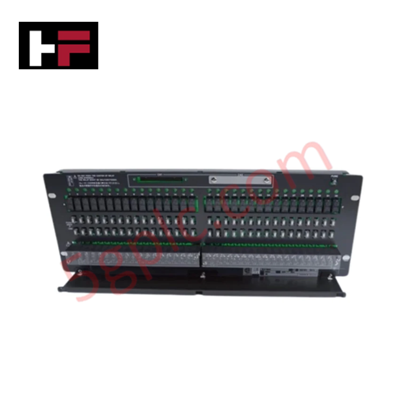
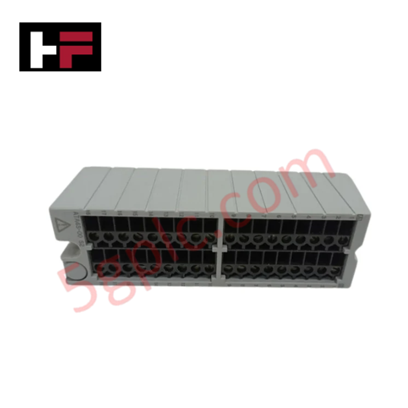
Carrier Compatibility: This module is intended for use in specific analog I/O carrier boxes (such as the AMN34). Ensure the module is firmly seated and the locking mechanism is engaged to maintain backplane connectivity.
Frequently Asked Questions (FAQ)
Q: What does "Pair and Spare" technology mean for this module?A: "Pair and Spare" is a redundancy architecture where two processor modules operate in synchronization (Pair), and if one fails, the other takes over instantly without interruption. The AMM42 supports this by providing reliable input data to both sides of the redundant system simultaneously.
Q: Can I use the AMM42 in a non-redundant system?A: While technically possible, the AMM42 is optimized for redundant Field Control Stations. Using it in a non-redundant configuration may not utilize its full capabilities and might require specific engineering settings.
Q: Is the AMM42 isolated?A: No. The specifications state there is no isolation between the system and field or between channels. You must ensure proper system grounding to avoid interference.
Q: What is the input resistance if I am using a barrier?A: When connected to a barrier, the input resistance should be modified to 70 Ω to ensure the correct voltage drop and signal transmission.
Additional Information
- 100% Genuine Parts: All products are original and authentic, ensuring reliable industrial performance.
- 30-Day Refund Guarantee: Return any in-stock item within 30 days in original, unopened packaging for a full refund (excluding shipping and fees).
- 12-Month Warranty: Covers defects in materials or workmanship; excludes misuse, normal wear, or unauthorized modifications.
- Worldwide Shipping: We ship via USPS, UPS, FedEx, and DHL. Delivery times vary by country and may be subject to customs or import fees.
- Support & Contact: Technical and warranty assistance is available anytime. Contact us here: Contact.
- Purchase Guidance: Check product specifications and compatibility carefully before ordering to ensure proper application.


Tech & Buying Guide

Essential Motion Control Commands: A Practical Guide for Engineers
Automation engineers often rely on precise position and speed control to drive modern factory machinery. Modern industrial systems, such as Programmable Logic Controllers (PLCs) and Distributed Control Systems (DCS), depend heavily on standardized motion instructions. Mastering these commands ensures operational safety, protects mechanical components, and optimizes cycle times across production lines.

Mastering Modern Industrial Joystick Controls in Heavy Automation
Industrial joysticks play a pivotal role in human-machine interaction across heavy material handling and mobile hydraulics. These tactile controllers translate complex operator movements into precise electrical signals for PLCs, motion controllers, and DCS networks. Consequently, selecting and installing the right joystick architecture ensures operator safety, reduces fatigue, and optimizes equipment performance.

Navigating Industrial Automation Failures: Types, Causes, and Mitigation Strategies
Modern manufacturing relies heavily on automated control systems to maximize throughput and maintain product quality. However, unplanned downtime in industrial automation can cost facility operators thousands of dollars per hour. Understanding how programmable logic controllers (PLCs), distributed control systems (DCS), and field instrumentation fail empowers engineering teams to implement robust preventive maintenance strategies.