










Product Details
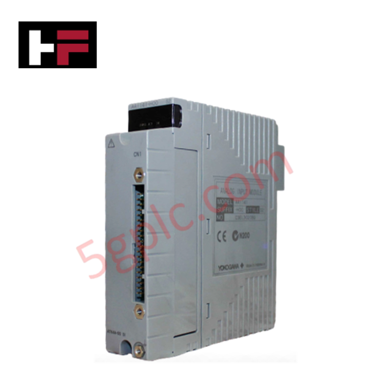
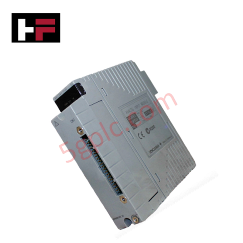
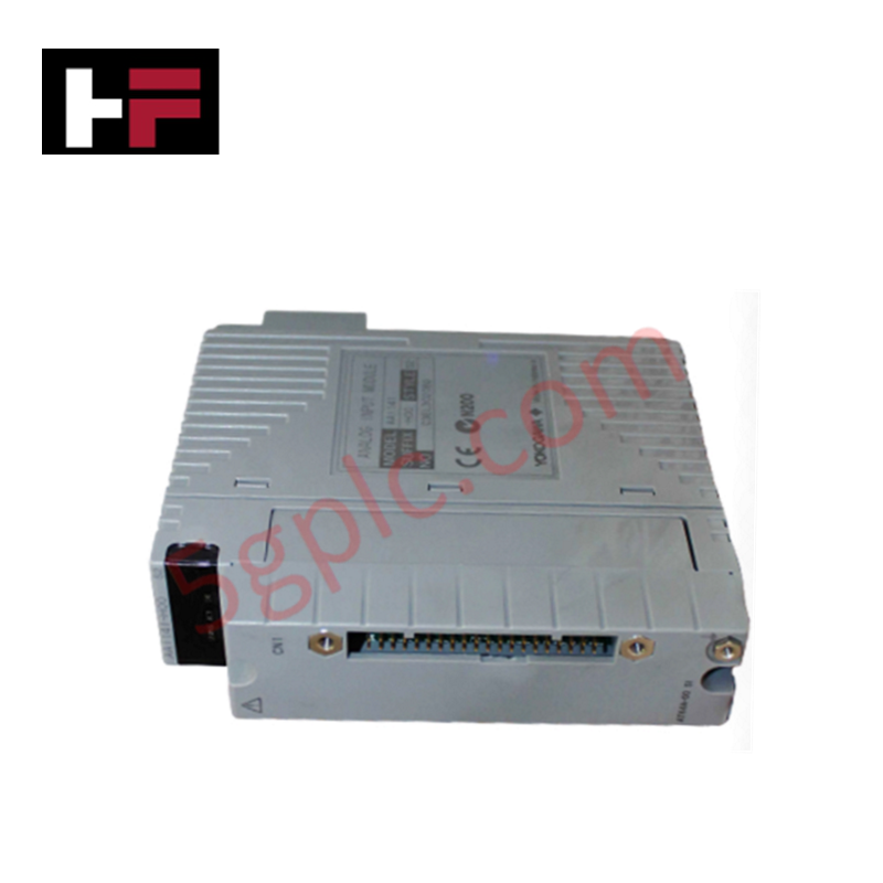
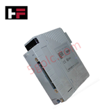
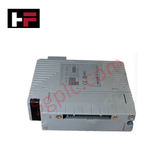
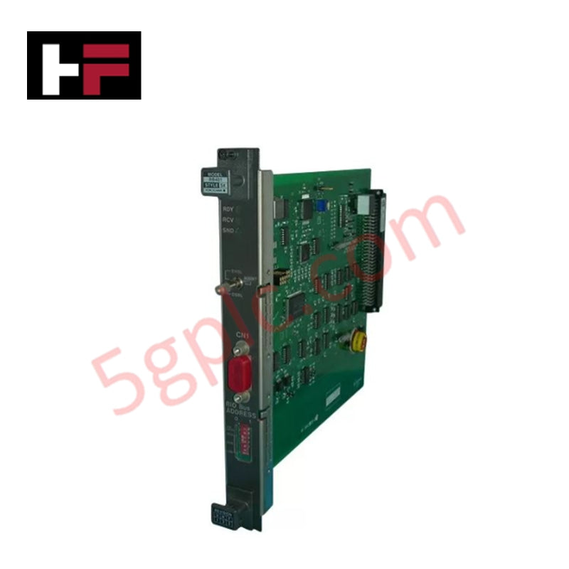
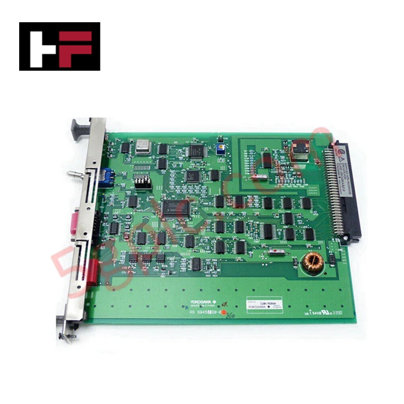
The YOKOGAWA AAI141-H00 S2, also cataloged as the AAI141 Analog Input Module, operates as a dedicated hardware component for 16-channel 4-20 mA DC and 1-5 VDC signal acquisition within YOKOGAWA CENTUM DCS networks. The module digitizes process variables with a 10 ms data update period and a 100 ms step response time for system processing.
Hardware Specifications
| Parameter | Specification |
|---|---|
| Model | AAI141-H00 S2 / AAI141-H00 |
| Brand | YOKOGAWA |
| Origin | Japan |
| Weight | 0.2 kg |
| Power Consumption | 310 mA (5 VDC), 450 mA (24 VDC) |
| Channel Count | 16 channels, non-isolated |
| Input Signal Types | 4 to 20 mA DC, 1 to 5 V DC |
| Common Mode Voltage | +/-1 VDC or less |
| Allowable Input Current | Up to 27 mA |
| Measurement Accuracy | +/-16 uA |
| Data Update Period | 10 ms |
| Step Response Time | 100 ms |
| Temperature Drift | +/-16 uA per 10 deg C |
| Transmitter Power Supply | >= 14.8 VDC (at 20 mA), <= 26.4 VDC (at 0 mA) |
| Input Resistance (Power ON) | 400 ohm (at 20 mA) to 1000 ohm (at 4 mA) |
| Input Resistance (Power OFF) | 500 k-ohm or larger |
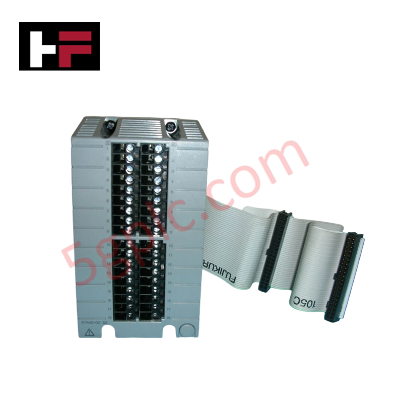
| External Connections | Pressure clamp terminal, KS cable, MIL connector cable |
4-20 mA HART Loop Protocol and Field Instrumentation
The AAI141-H00 S2 supports 16 non-isolated input channels capable of powering two-wire transmitters with supply voltages from 14.8 VDC (at 20 mA) up to 26.4 VDC (at 0 mA). Digital telemetry data pass through via 4-20 mA HART loop protocol superimposed over standard analog current signals. The module maintains an input resistance between 400 ohm and 1000 ohm during power-on operation, switching to a high-impedance state exceeding 500 k-ohm during power-off conditions to prevent circuit loading on adjacent field instrumentation loops.
Frequently Asked Questions
Q: What is the input resistance behavior of the AAI141-H00 S2 during powered and unpowered states?
A: When powered on, the module maintains an input resistance between 400 ohm (at 20 mA) and 1000 ohm (at 4 mA). When powered off, the input resistance increases to 500 k-ohm or higher.
Q: Does the AAI141-H00 S2 provide loop power to external field transmitters?
A: Yes, the module supplies integrated transmitter power rated at 14.8 VDC or higher at 20 mA, and 26.4 VDC or lower at 0 mA.
Q: What connection hardware options are supported for external signal wiring?
A: External wiring interfaces with pressure clamp terminals, KS cables, or MIL connector cables depending on the termination block assembly used.
Field Installation Guidelines
De-energize backplane rack power prior to inserting or removing the AAI141-H00 S2 module. Observe electrostatic discharge (ESD) safety procedures by wearing a grounded wrist strap during card handling. Insert the module into the CENTUM I/O slot until the backplane connectors seat completely, then tighten top and bottom retaining screws to establish frame ground continuity. Ensure that common-mode voltage across signal channels remains within +/-1 VDC. Connect field wiring using pressure clamp terminal blocks, KS cables, or MIL connector cables. Route analog signal lines in shielded twisted-pair cables and bond the shield wire at a single earth ground termination point inside the cabinet panel.
Additional Information
- 100% Genuine Parts: All products are original and authentic, ensuring reliable industrial performance.
- 30-Day Refund Guarantee: Return any in-stock item within 30 days in original, unopened packaging for a full refund (excluding shipping and fees).
- 12-Month Warranty: Covers defects in materials or workmanship; excludes misuse, normal wear, or unauthorized modifications.
- Worldwide Shipping: We ship via USPS, UPS, FedEx, and DHL. Delivery times vary by country and may be subject to customs or import fees.
- Support & Contact: Technical and warranty assistance is available anytime. Contact us here: Contact.
- Purchase Guidance: Check product specifications and compatibility carefully before ordering to ensure proper application.


Tech & Buying Guide

Industrial Networking Essentials: Demystifying Hubs, Switches, and Routers in Control Systems
Industrial automation relies heavily on robust networking infrastructure to connect programmable logic controllers (PLCs), distributed control systems (DCS), and human-machine interfaces (HMIs). Modern factory automation environments generate vast amounts of real-time operational data across deterministic networks. Understanding the structural differences between hubs, switches, and routers ensures optimal traffic segmentation, minimizes latency, and maintains high network availability.

Safety Relays in Industrial Automation: Fundamentals, Design Standards, and Fail-Safe Architecture
Safety relays form the bedrock of functional safety in modern factory automation, preventing catastrophic equipment failure and protecting plant personnel. While standard electromechanical relays handle basic load switching, they lack the redundant diagnostics required for high-risk industrial environments. Modern industrial automation platforms—including programmable logic controllers (PLCs) and distributed control systems (DCS)—rely on specialized safety relays to monitor field devices and isolate hazards instantly.

Voice-Activated Industrial Automation: Integrating Speech Control into PLC and DCS Architectures
Industrial automation integrates speech recognition, IIoT protocols, and NLP with PLCs and DCS to streamline operations. By leveraging advanced edge computing, engineers enable real-time, hands-free control—allowing personnel to manage smart factory processes safely away from hazardous equipment.