


Product Details
Product Overview
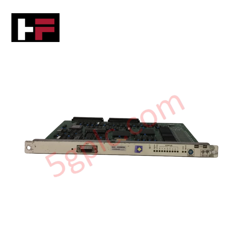
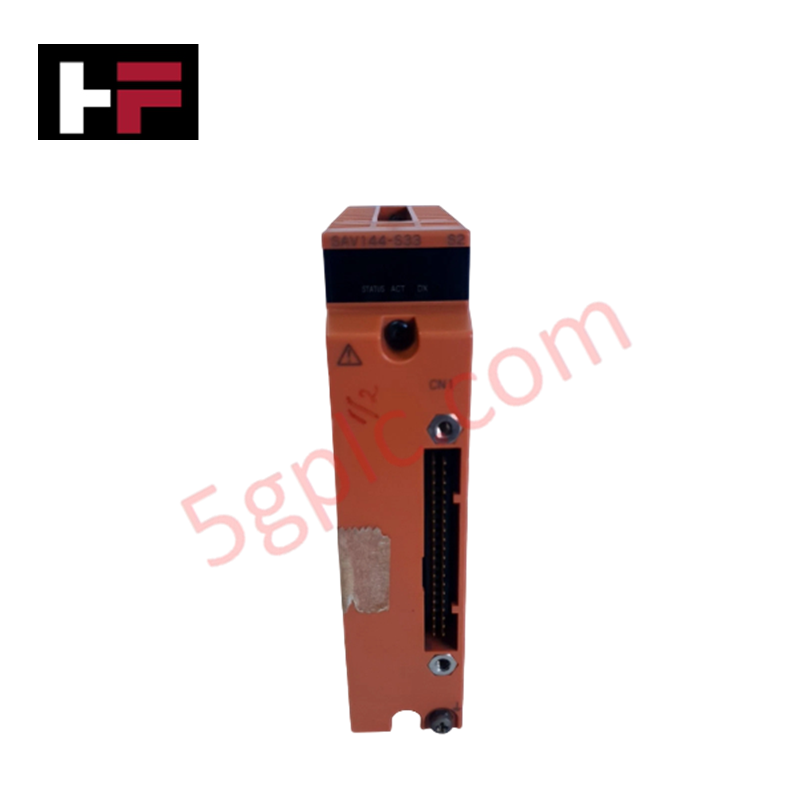
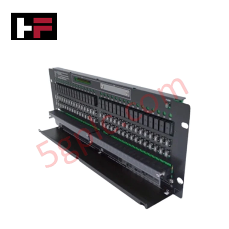
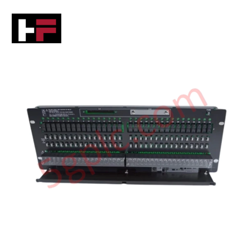
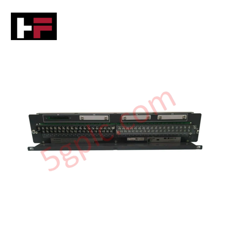
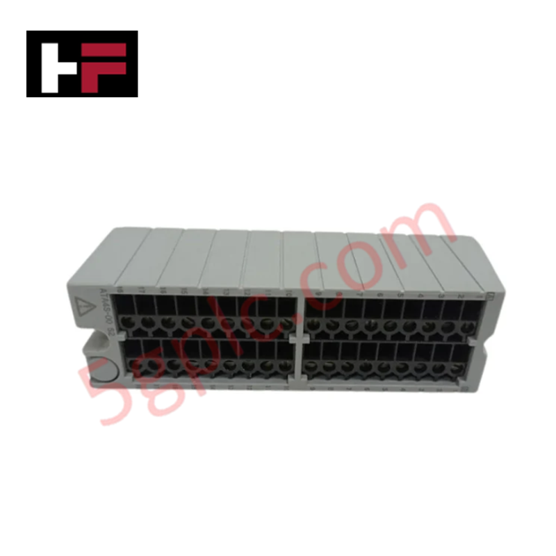
The Yokogawa EC401-10 ESB Bus Coupler Module delivers high-speed, deterministic communication between CENTUM VP Field Control Stations and distributed I/O racks via the Enhanced Serial Bus (ESB) architecture. It resolves the challenge of extending reliable I/O connectivity in compact or modular control cabinets by supporting up to nine downstream I/O units within a 10-meter range. With a dedicated 128 Mbps transmission speed optimized for process data, the EC401-10 ensures minimal latency for critical control loops in power generation, oil and gas, and chemical processing applications. Its lightweight, space-efficient design simplifies panel layout while maintaining the robustness required for continuous industrial operation.
Technical Specifications
|
Parameter |
Specification |
|---|---|
|
Product Type |
ESB Bus Coupler Module |
|
Brand / Series |
Yokogawa / CENTUM VP Compatible |
|
Model |
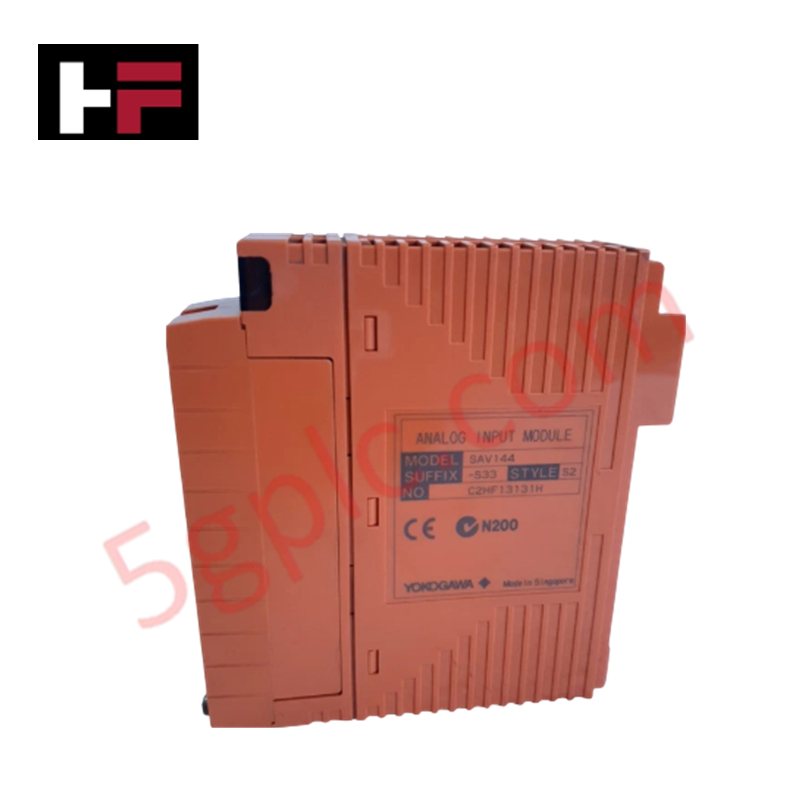
EC401-10 |
|
Primary Function |
ESB Bus Interface for I/O Module Communication |
|
Connectable Units |
Maximum 9 I/O modules per coupler |
|
Transmission Speed |
128 Mbps (dedicated I/O data channel) |
|
Transmission Distance |
Maximum 10 meters between coupler and I/O units |
|
Current Consumption |
0.5 A (for N-IO/FIO, 1-Port configuration) |
|
Weight |
Approximately 0.24 kg (0.53 lbs) |
|
Explosion Protection |
Standard type (non-hazardous location) / Basic type |
|
Mounting |
DIN rail or dedicated node slot (CENTUM VP compatible) |
|
Bus Architecture |
ESB (Enhanced Serial Bus) for deterministic I/O scanning |
|
Target Applications |
Process control, power plants, refinery I/O expansion |
Model Code Decomposition
The Yokogawa EC401-10 follows the structured naming convention used for CENTUM VP ESB bus components. The suffix provides immediate insight into the module's protection rating and functional variant.
Part Number: EC401-10
-
EC: Series identifier for ESB Bus communication modules within Yokogawa's CENTUM architecture.
-
401: Functional code specifying the ESB Bus Coupler role for connecting I/O racks to the Field Control Station.
-
-10: Variant suffix defining hardware configuration and certification:
-
First digit (1): Explosion protection classification → "1" = Standard type (no explosion protection), suitable for general industrial panels.
-
Second digit (0): Functional revision/base type → "0" = Basic configuration with single-port ESB interface and standard current rating (0.5 A).
-
Note: Alternative suffixes (e.g., -00, -21) may indicate intrinsically safe variants, dual-port redundancy, or regional certifications. Always verify the full suffix against project specifications and Yokogawa's certification documentation.
Installation Recommendations and Wiring Guidelines
Mount the EC401-10 securely on a 35mm DIN rail or within the designated CENTUM VP node slot, ensuring adequate clearance for ESB cable routing. Maintain the maximum 10-meter transmission distance between the coupler and the farthest I/O module to guarantee signal integrity at 128 Mbps.
Use Yokogawa-specified ESB cables with proper shielding and connector types (typically proprietary multi-conductor or twisted-pair with locking connectors). Terminate connections firmly to prevent intermittent communication faults. For systems requiring redundancy, install dual EC401-10 modules configured in hot-standby mode, with physically separated cable paths to mitigate single-point failure risks. Power the module from a regulated 24 VDC supply capable of delivering at least 0.5 A per coupler, plus margin for connected I/O units. After installation, verify communication status via the module's LED indicators: a steady green light confirms successful ESB handshake with the FCS, while blinking amber may indicate configuration mismatches or cable faults. Perform a loopback test using CENTUM VP engineering tools before commissioning to validate end-to-end I/O scanning performance.
Frequently Asked Questions (FAQ)
Q: Can the EC401-10 connect to third-party I/O modules?
A: No. The EC401-10 is designed exclusively for Yokogawa CENTUM VP-compatible I/O modules using the proprietary ESB protocol. Third-party I/O integration requires a separate protocol gateway or remote I/O adapter that translates to standard fieldbus formats.
Q: What is the practical limit for the number of I/O points per EC401-10?
A: While the coupler supports up to 9 physical I/O units, the total point count depends on each module's density (e.g., 16-channel digital vs. 8-channel analog). Consult the CENTUM VP engineering manual to calculate scan time and bandwidth utilization for your specific configuration to ensure deterministic performance.
Q: Is the EC401-10 hot-swappable?
A: Yes, when installed in a CENTUM VP node with redundant configuration and proper system settings. However, best practice is to place the associated control station in maintenance mode via the engineering station before physical replacement to avoid transient I/O communication alarms.
Q: Can I extend the 10-meter transmission distance?
A: The 10-meter limit is defined by the ESB electrical specification at 128 Mbps. For longer distances, consider using fiber-optic ESB extenders (if supported by your system version) or relocating the I/O rack closer to the Field Control Station. Do not exceed the specified distance without Yokogawa-approved extension hardware.
Q: How does the explosion protection rating affect installation?
A: The EC401-10 with suffix "-10" is a standard type for non-hazardous locations. For installations in classified hazardous areas (e.g., Zone 2, Class I Div 2), select a variant with appropriate intrinsic safety or explosion-proof certification (e.g., suffix "-21" or "-30") and follow all local electrical codes for hazardous location wiring and enclosure requirements.
Additional Information
- 100% Genuine Parts: All products are original and authentic, ensuring reliable industrial performance.
- 30-Day Refund Guarantee: Return any in-stock item within 30 days in original, unopened packaging for a full refund (excluding shipping and fees).
- 12-Month Warranty: Covers defects in materials or workmanship; excludes misuse, normal wear, or unauthorized modifications.
- Worldwide Shipping: We ship via USPS, UPS, FedEx, and DHL. Delivery times vary by country and may be subject to customs or import fees.
- Support & Contact: Technical and warranty assistance is available anytime. Contact us here: Contact.
- Purchase Guidance: Check product specifications and compatibility carefully before ordering to ensure proper application.


Tech & Buying Guide

Essential Motion Control Commands: A Practical Guide for Engineers
Automation engineers often rely on precise position and speed control to drive modern factory machinery. Modern industrial systems, such as Programmable Logic Controllers (PLCs) and Distributed Control Systems (DCS), depend heavily on standardized motion instructions. Mastering these commands ensures operational safety, protects mechanical components, and optimizes cycle times across production lines.

Mastering Modern Industrial Joystick Controls in Heavy Automation
Industrial joysticks play a pivotal role in human-machine interaction across heavy material handling and mobile hydraulics. These tactile controllers translate complex operator movements into precise electrical signals for PLCs, motion controllers, and DCS networks. Consequently, selecting and installing the right joystick architecture ensures operator safety, reduces fatigue, and optimizes equipment performance.

Navigating Industrial Automation Failures: Types, Causes, and Mitigation Strategies
Modern manufacturing relies heavily on automated control systems to maximize throughput and maintain product quality. However, unplanned downtime in industrial automation can cost facility operators thousands of dollars per hour. Understanding how programmable logic controllers (PLCs), distributed control systems (DCS), and field instrumentation fail empowers engineering teams to implement robust preventive maintenance strategies.