


Product Details
Product Overview
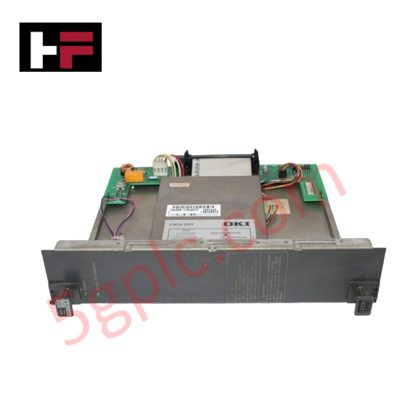
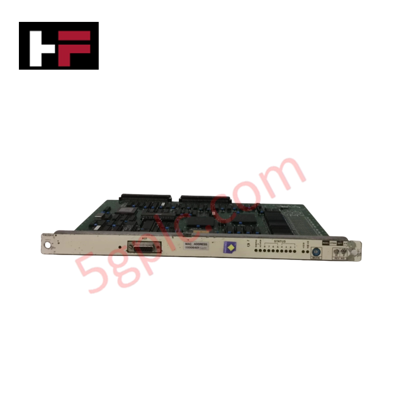
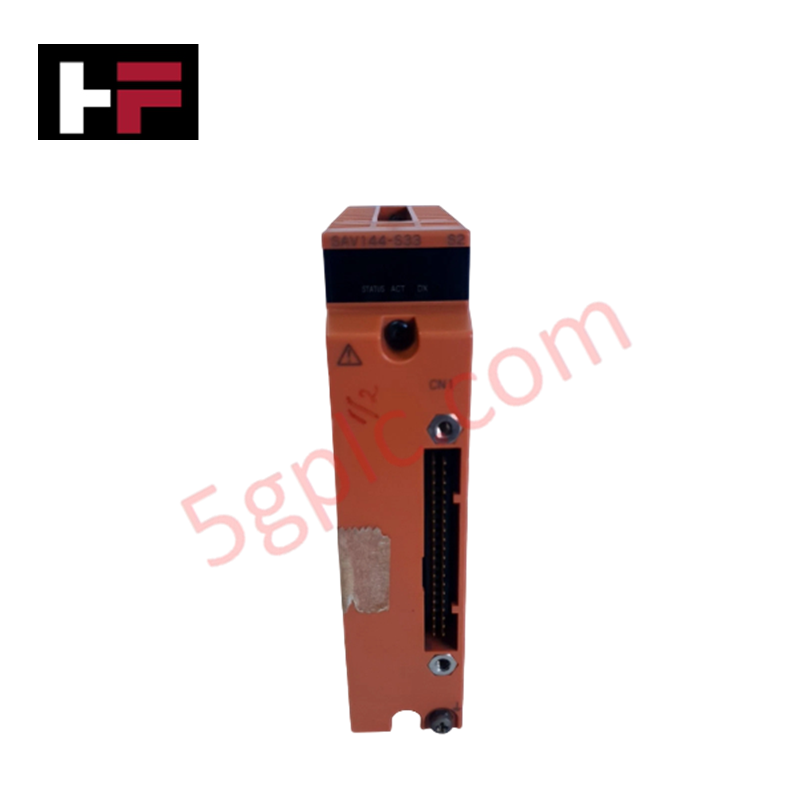
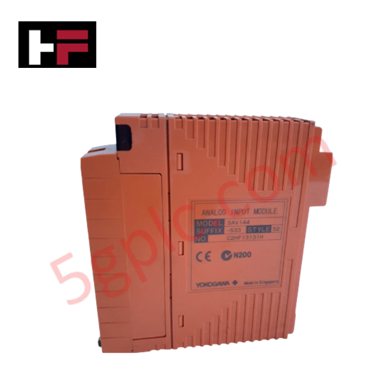
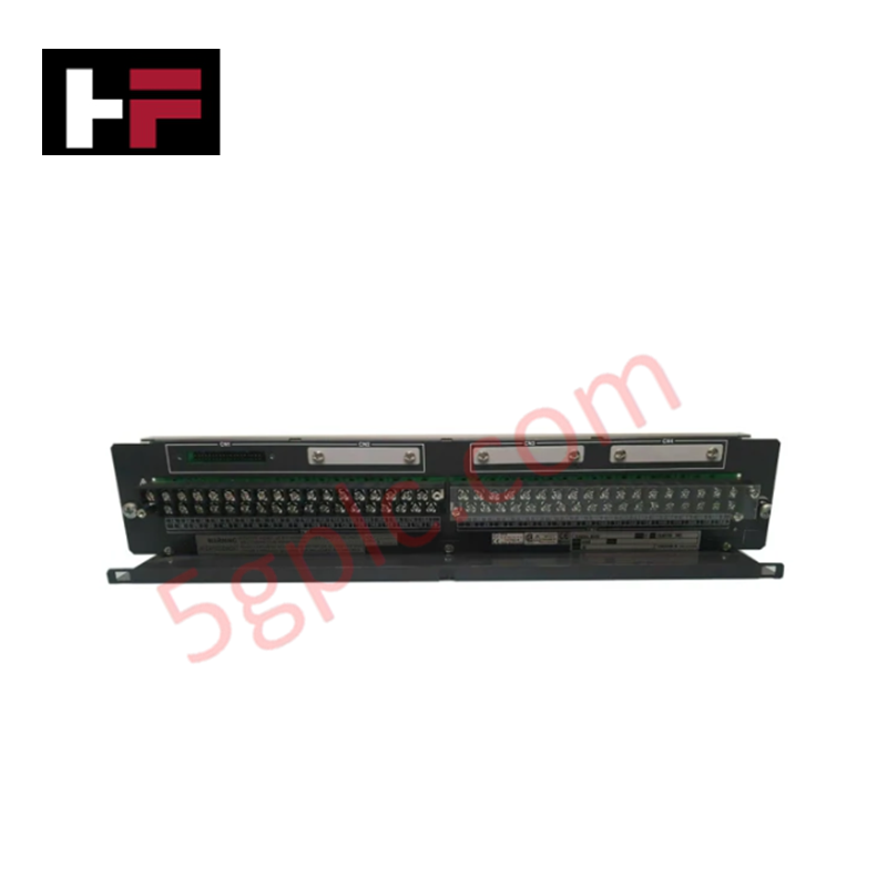
The Yokogawa AIP444-S1 is a high-density, multi-function analog input module engineered for the CENTUM VP and CS 3000 Distributed Control Systems (DCS). In complex process environments where temperature, pressure, and level variables must be monitored with extreme precision, this module solves the challenge of signal diversity by accepting Thermocouple (TC), Resistance Temperature Detector (RTD), and DC Voltage inputs on a single card. Featuring 8 fully isolated channels, the AIP444-S1 eliminates ground loop errors and ensures data integrity even in electrically noisy industrial settings. Its compact design maximizes cabinet space efficiency while delivering the reliability required for continuous operation in power generation, petrochemical refining, and pharmaceutical manufacturing.
Technical Specifications
|
Parameter |
Specification |
|---|---|
|
Model Number |
AIP444 |
|
Style Code |
S1 |
|
Manufacturer |
Yokogawa Electric Corporation |
|
Module Type |
Multi-Input Analog Input Module |
|
System Compatibility |
CENTUM VP, CENTUM CS 3000 |
|
Channel Count |
8 Channels (Isolated) |
|
Input Signal Types |
Thermocouple (TC), RTD, DC Voltage (mV/V) |
|
Input Isolation |
Channel-to-Channel and Channel-to-Bus Isolation |
|
Conversion Accuracy |
±0.1% of span (Typical, dependent on sensor type) |
|
Cold Junction Compensation |
Automatic internal compensation for TC inputs |
|
Power Consumption |
Low power design (Optimized for high-density nodes) |
|
Dimensions (H×W×D) |
130 mm × 30 mm × 100 mm |
|
Unit Weight |
Approx. 0.25 kg |
|
Operating Temperature |
0°C to 50°C (32°F to 122°F) |
|
Storage Temperature |
-20°C to 70°C |
|
Mounting Style |
Backplane Mount (CENTUM VP Node) |
|
Hot-Swapping |
Supported (Non-disruptive replacement) |
|
Diagnostic Features |
Wire break detection, Over-range/Under-range alarms |
Model Code Decomposition
Yokogawa's CENTUM VP I/O modules utilize a strict naming convention where the base part number defines the electrical function, and the "Style" suffix indicates the hardware revision, component sourcing, and firmware compatibility. Using the correct style is critical for system recognition.
Part Number: AIP444-S1
-
AI: Identifies the hardware series within the Yokogawa CENTUM VP family, specifically for standard I/O and interface units.
-
P: Denotes the "Processor" or "Interface" functional category. This indicates a smart I/O module with onboard microprocessors responsible for signal linearization, cold junction compensation (for TCs), and digital filtering.
-
444: The unique designator for the 8-channel Multi-Input Analog Unit.
-
The first "4" typically correlates to Analog Input types capable of handling low-level signals (mV, TC, RTD).
-
The "44" sequence specifies the 8-channel density and the versatility to accept multiple sensor types (TC/RTD/Voltage) via software configuration.
-
-S1 (Style 1): This suffix is mandatory and indicates the specific hardware revision level.
-
S1: Represents the initial or primary production revision of the AIP444. It defines the specific analog-to-digital converter (ADC) architecture, isolation barrier components, and firmware map compatible with CENTUM VP R3.x and later stations.
-
Compatibility Logic: Substituting an S1 module with a different style (e.g., S2, S3) without verifying backplane compatibility may result in the station failing to recognize the card or reporting hardware errors. The "S1" ensures exact pin-out alignment and voltage tolerance matching the original system design.
Installation Recommendations and Wiring Guidelines
Proper installation of the AIP444-S1 is essential to maintain the accuracy of low-level temperature and voltage signals and to leverage its isolation features.
-
Software Configuration First: Before wiring, use the CENTUM VP engineering tool (Vx-Toolset) to configure each of the 8 channels for the specific sensor type (e.g., Type K Thermocouple, Pt100 RTD, or 1-5V). The module does not auto-detect sensor types; incorrect software settings will yield erroneous readings.
-
Cable Selection:
-
Thermocouples: Use compensated extension wires matched to the thermocouple type (e.g., KX for Type K) to prevent measurement errors at the terminal block.
-
RTDs: Use 3-wire or 4-wire shielded cables to compensate for lead resistance.
-
Shielding: All signal cables must be shielded twisted pair. Ground the shield at the control room end only (single-point grounding) to utilize the module's channel isolation effectively and prevent ground loops.
-
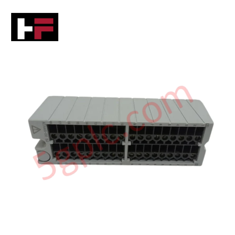
Terminal Wiring: Connect sensors to the front terminal block. Ensure tight connections (torque approx. 0.5 N·m) to prevent contact resistance, which is critical for low-resistance RTD measurements.
-
Cold Junction Reference: The AIP444 measures internal temperature for Cold Junction Compensation (CJC). Ensure the module is not installed directly adjacent to high-heat sources (like power supplies) within the rack, as localized heating can affect TC accuracy.
-
Noise Mitigation: Keep analog signal wiring separate from high-voltage AC lines and variable frequency drive (VFD) outputs. Maintain a minimum separation of 20 cm to prevent electromagnetic interference (EMI) from corrupting low-level mV signals.
-
Hot-Swap Procedure: While the module supports hot-swapping, it is best practice to force the associated tags to "Hold" or "Manual" mode in the operator station before removal to prevent process upsets during the brief communication interruption.
Frequently Asked Questions (FAQ)
Q: Can I mix different sensor types on the same AIP444-S1 module?
A: Yes. One of the key advantages of the AIP444-S1 is its flexibility. You can configure Channel 1 for a Type J Thermocouple, Channel 2 for a Pt100 RTD, and Channel 3 for a 0-10V signal simultaneously. Each channel is configured independently via the Vx-Toolset software.
Q: Does this module support 2-wire RTDs?
A: Yes, the AIP444-S1 supports 2-wire, 3-wire, and 4-wire RTD configurations. However, for highest accuracy, 3-wire or 4-wire connections are recommended to eliminate lead wire resistance errors. The software must be set to match the physical wiring scheme.
Q: What happens if a thermocouple wire breaks?
A: The AIP444-S1 includes built-in burnout detection. If a wire break occurs, the module detects the open circuit and drives the input value to a predefined "Upscale" or "Downscale" limit (configurable in software), triggering an immediate alarm in the DCS to alert operators.
Q: Is the AIP444-S1 compatible with older CENTUM CS 1000 systems?
A: The AIP444 series is primarily designed for CENTUM VP and CS 3000 architectures. While some backward compatibility exists depending on the node type, it is not natively supported in legacy CS 1000 slots without specific adapter nodes or firmware upgrades. Always verify compatibility with your specific FCS model.
Q: Do you supply this module as new or refurbished?
A: We supply 100% brand-new, original factory-sealed Yokogawa AIP444-S1 modules. We do not sell refurbished or pulled units for critical control applications to ensure maximum reliability and warranty coverage.
Q: What is the lead time for shipping?
A: We maintain stock of the AIP444-S1 for immediate dispatch. Orders are typically processed and shipped via DHL/FedEx within 24 to 72 hours, with global delivery usually achieved within 3-5 business days.
Additional Information
- 100% Genuine Parts: All products are original and authentic, ensuring reliable industrial performance.
- 30-Day Refund Guarantee: Return any in-stock item within 30 days in original, unopened packaging for a full refund (excluding shipping and fees).
- 12-Month Warranty: Covers defects in materials or workmanship; excludes misuse, normal wear, or unauthorized modifications.
- Worldwide Shipping: We ship via USPS, UPS, FedEx, and DHL. Delivery times vary by country and may be subject to customs or import fees.
- Support & Contact: Technical and warranty assistance is available anytime. Contact us here: Contact.
- Purchase Guidance: Check product specifications and compatibility carefully before ordering to ensure proper application.


Tech & Buying Guide

Essential Motion Control Commands: A Practical Guide for Engineers
Automation engineers often rely on precise position and speed control to drive modern factory machinery. Modern industrial systems, such as Programmable Logic Controllers (PLCs) and Distributed Control Systems (DCS), depend heavily on standardized motion instructions. Mastering these commands ensures operational safety, protects mechanical components, and optimizes cycle times across production lines.

Mastering Modern Industrial Joystick Controls in Heavy Automation
Industrial joysticks play a pivotal role in human-machine interaction across heavy material handling and mobile hydraulics. These tactile controllers translate complex operator movements into precise electrical signals for PLCs, motion controllers, and DCS networks. Consequently, selecting and installing the right joystick architecture ensures operator safety, reduces fatigue, and optimizes equipment performance.

Navigating Industrial Automation Failures: Types, Causes, and Mitigation Strategies
Modern manufacturing relies heavily on automated control systems to maximize throughput and maintain product quality. However, unplanned downtime in industrial automation can cost facility operators thousands of dollars per hour. Understanding how programmable logic controllers (PLCs), distributed control systems (DCS), and field instrumentation fail empowers engineering teams to implement robust preventive maintenance strategies.