










Product Details
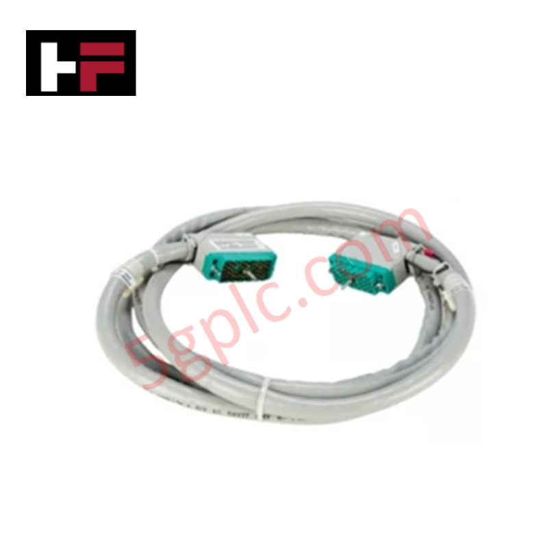
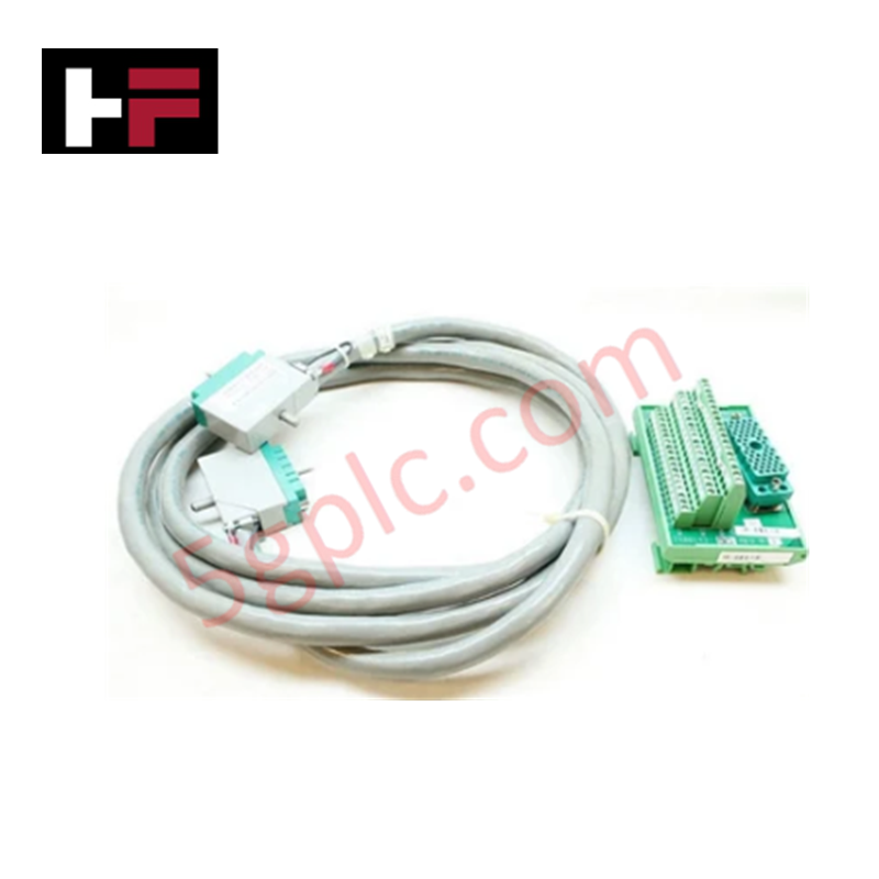
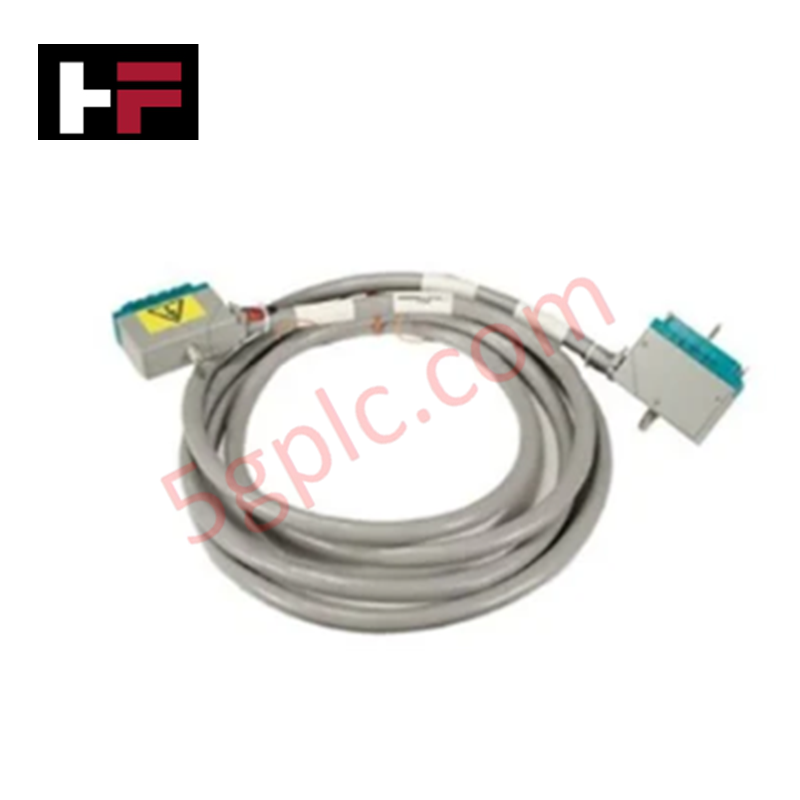
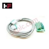
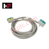
The Triconex 4000103-516, also cataloged as the 4000103 Cable Assembly, operates as a dedicated hardware component for high-integrity signal interconnection and system backplane extension within Tricon CX platforms. It routes high-speed data communications and 24 VDC auxiliary power across chassis racks, supporting fault-tolerant peer-to-peer networking and sequence of events (SOE) timestamp synchronization.
Hardware Specifications
| Parameter | Specification |
|---|---|
| Model | 4000103-516 |
| Brand | Triconex (Invensys / Schneider Electric) |
| Origin | USA |
| Dimensions | 100 mm x 50 mm x 10 mm |
| Operating Temp | -40 deg C to +85 deg C |
| Power Consumption | Operating Voltage: 24 VDC |
| Cable Length | 10 feet (approx. 3 meters) |
| Protocol Support | Modbus TCP/IP pass-through / peer-to-peer |
| System Compatibility | Tricon CX Safety Instrumented Systems |
Triple Modular Redundancy (TMR) 2oo3 Architecture and Fail-Safe State Execution
The Triconex 4000103-516 cable assembly provides redundant conductor paths required to maintain triple modular redundancy (TMR) 2oo3 architecture across distributed I/O racks. Galvanic isolation and shielded differential pair grouping prevent external noise coupling from interfering with 1 ms SOE event timestamping or board-level voting algorithms. By preserving physical bus continuity under hardware fault conditions, the cable infrastructure enables uninterrupted fail-safe state execution and maintains SIL3 system compliance across all connected chassis nodes.
Frequently Asked Questions
Q: Does the 4000103-516 cable assembly support hot-swap maintenance procedures on connected I/O racks?
A: Yes, in a redundant dual-cable bus topology, individual cable assemblies can be disconnected and replaced online without interrupting system backplane power or halting active processor operations.
Q: How does the cable construction prevent electromagnetic interference across long parallel runs?
A: The assembly incorporates overall foil and braided shield layers around internal twisted pairs, providing physical galvanic isolation against high-voltage transient coupling in cabinet wireways.
Q: What input voltage level is maintained through the internal power conductors of the assembly?
A: The internal power leads are rated to carry regulated 24 VDC system power across backplane sub-assemblies over the standard 10-foot cable length.
Field Installation Guidelines
- Inspect the connector pins and locking screws of the 4000103-516 cable assembly for physical damage prior to insertion into the chassis interface port.
- Align the cable connector with the mating chassis receptacle and hand-tighten the retaining thumbscrews evenly to guarantee proper pin seating.
- Maintain a minimum bending radius of 50 mm along the cable run to prevent conductor fatigue and signal impedance mismatches.
- Bond cable shield drain wires directly to the cabinet instrumentation earth bar at both panel termination points to ensure maximum noise immunity.
Additional Information
- 100% Genuine Parts: All products are original and authentic, ensuring reliable industrial performance.
- 30-Day Refund Guarantee: Return any in-stock item within 30 days in original, unopened packaging for a full refund (excluding shipping and fees).
- 12-Month Warranty: Covers defects in materials or workmanship; excludes misuse, normal wear, or unauthorized modifications.
- Worldwide Shipping: We ship via USPS, UPS, FedEx, and DHL. Delivery times vary by country and may be subject to customs or import fees.
- Support & Contact: Technical and warranty assistance is available anytime. Contact us here: Contact.
- Purchase Guidance: Check product specifications and compatibility carefully before ordering to ensure proper application.
Tech & Buying Guide

Top 5 Operational Advantages of HMIs in Modern Factory Automation

Importance of Safety Barriers in PLC and DCS Control Systems
