


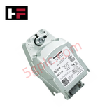
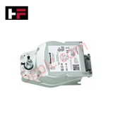
Product Details
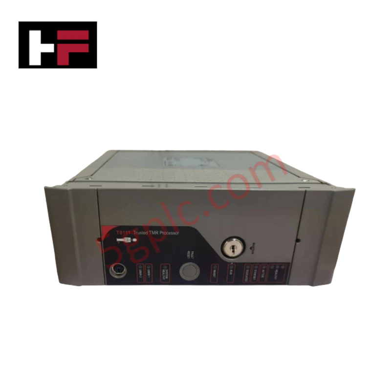
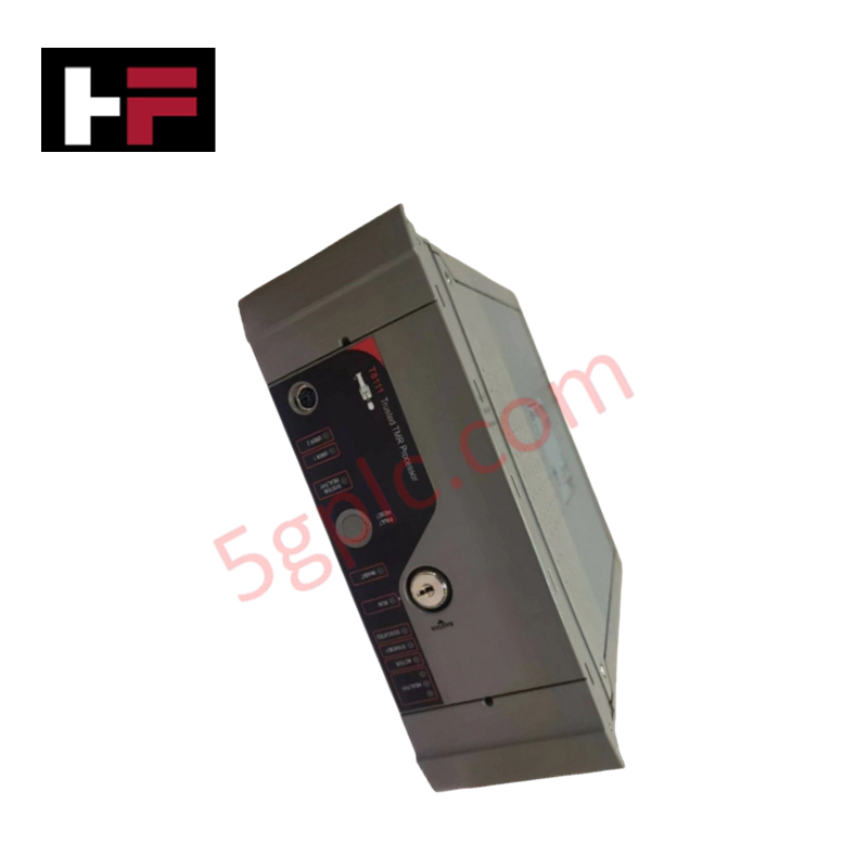
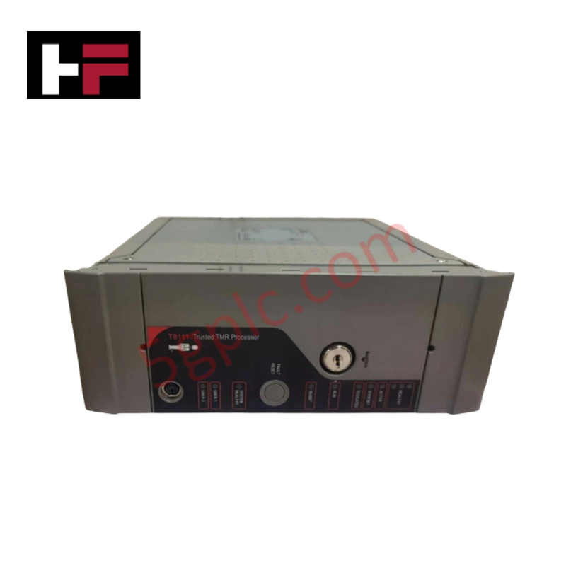
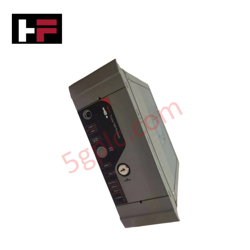
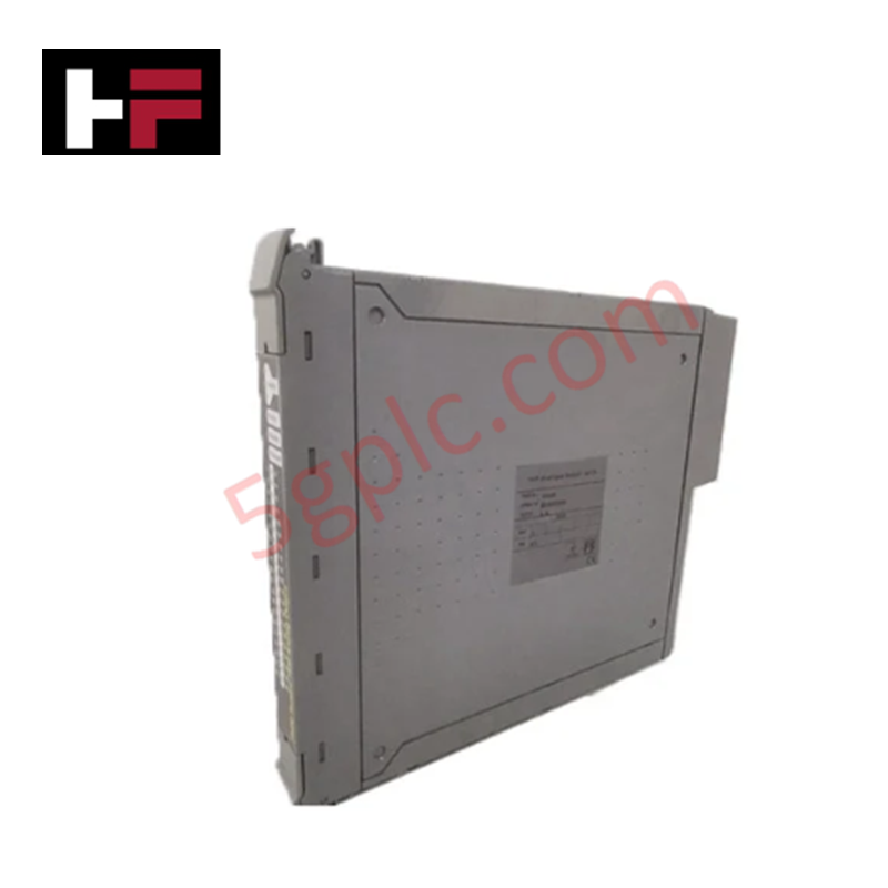
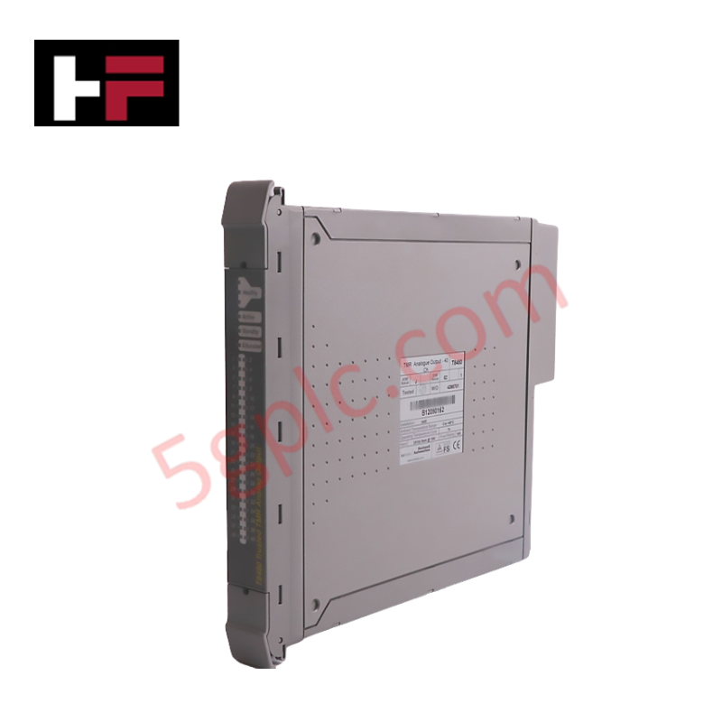
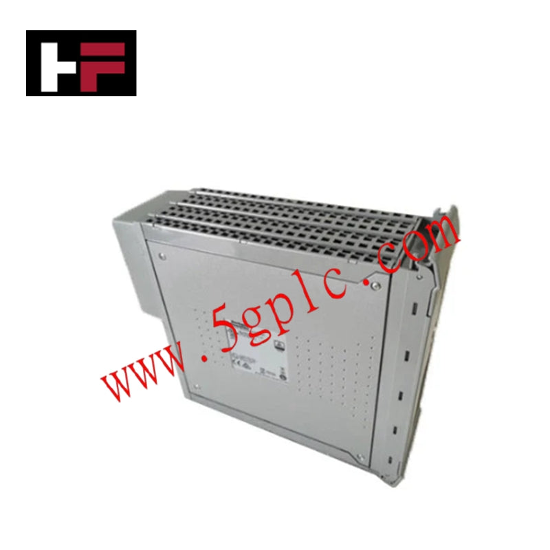
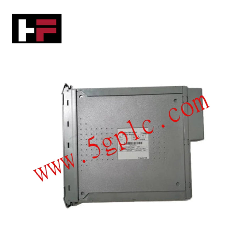
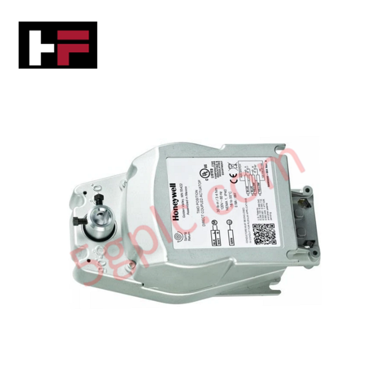
Configured for fire and smoke damper emergency control in HVAC safety networks, the Honeywell MS4609F1210, also cataloged as the MS4609F1210 Fire And Smoke Actuator, provides direct physical/electrical execution. It delivers high torque output and spring return functionality to drive dampers into safe positions during emergency events.
Hardware Specifications
| Parameter | Specification |
|---|---|
| Model | MS4609F1210 |
| Brand | Honeywell |
| Origin | Standard Industrial Manufacturing |
| Weight | Standard Actuator Form Factor |
| Dimensions | Direct Coupled to 1/2-inch Round Shaft |
| Operating Temp | -18 deg C to 55 deg C (0°F to 130°F) |
| Power Consumption | 230 V AC Supply Input |
| Torque Output | 80 in-lb (9 Nm) |
| Spring Return Time | 15-20 seconds |
Channel-to-Channel Isolation and Loop Protocol
The architecture of the Honeywell MS4609F1210 incorporates robust channel-to-channel isolation and supports 4-20 mA HART loop protocol integration pathways or auxiliary dry contact feedback loops where applicable. By maintaining electrical separation between the 230 V AC motor drive circuit and the two SPST auxiliary switches (rated for 5A resistive / 3A inductive at 250 V AC), the unit prevents high-voltage feedback into low-voltage auxiliary monitoring circuits. Furthermore, cold junction compensation considerations and internal relay isolation ensure reliable position feedback transmission across safety interlocking networks.
Frequently Asked Questions
Q: What is the primary function of the spring return mechanism in the Honeywell MS4609F1210?
A: It provides mechanical energy storage during powered opening, allowing the actuator to close the damper automatically within 15-20 seconds upon power loss or emergency interlock trip.
Q: Can this actuator be serviced or replaced while the 230 V AC power supply is active?
A: Live electrical maintenance on 230 V AC damper actuators presents severe electrical shock hazards. Power must be fully isolated and locked out prior to physical removal or wiring adjustments.
Q: How do the auxiliary switches provide feedback to the building management system?
A: The two built-in SPST auxiliary switches change state based on actuator rotation position, providing discrete dry contact verification of damper open or closed status.
Field Installation Guidelines
- Shaft Mounting: Mount the actuator directly onto a 1/2-inch round damper shaft, ensuring the anti-rotation bracket is secured to prevent housing displacement during operation.
- Power Wiring: Connect the 230 V AC supply lines to the designated motor terminals, ensuring proper phasing and adherence to local electrical safety codes.
- Auxiliary Switch Cabling: Route auxiliary switch wiring separately from high-voltage motor power cables to prevent induced electrical noise on feedback loops.
- Environmental Protection: Ensure the installation location remains within the specified temperature range of -18 deg C to 55 deg C and protects against direct moisture exposure.
Additional Information
- 100% Genuine Parts: All products are original and authentic, ensuring reliable industrial performance.
- 30-Day Refund Guarantee: Return any in-stock item within 30 days in original, unopened packaging for a full refund (excluding shipping and fees).
- 12-Month Warranty: Covers defects in materials or workmanship; excludes misuse, normal wear, or unauthorized modifications.
- Worldwide Shipping: We ship via USPS, UPS, FedEx, and DHL. Delivery times vary by country and may be subject to customs or import fees.
- Support & Contact: Technical and warranty assistance is available anytime. Contact us here: Contact.
- Purchase Guidance: Check product specifications and compatibility carefully before ordering to ensure proper application.


Tech & Buying Guide

Comparing PID and Model Predictive Control (MPC) in Industrial Automation
Advanced process control strategies remain fundamental for maintaining optimal plant efficiency and product quality. Therefore, control engineers frequently evaluate whether a traditional Proportional-Integral-Derivative (PID) algorithm or a Model Predictive Control (MPC) strategy suits a given application. In my 15 years of commissioning distributed control systems (DCS) and factory automation networks, I have tuned thousands of PID loops while deploying complex MPC packages on multivariable distillation columns. Below, I break down the core operational differences between these two foundational control methodologies.
Mastering Time Synchronization in Industrial Automation Applications
Precise time synchronization remains vital for modern industrial automation, distributed control systems (DCS), and power protection networks. Therefore, control engineers must maintain uniform clocks across all controllers, human-machine interfaces (HMIs), and supervisory stations. In my 15 years of commissioning complex industrial automation projects, I have frequently investigated root-cause failures where misaligned timestamps obscured the true sequence of events. Below, I break down the core time synchronization protocols and methods essential for reliable factory automation.

Designing Robust SCADA Systems for Electrical Substation Automation
Electrical substation automation requires rigorous engineering standards to guarantee uninterrupted power distribution and grid stability. Therefore, control engineers must design supervisory control and data acquisition (SCADA) architectures with absolute precision. In my 15 years of commissioning power protection and substation automation systems, I have witnessed how meticulous SCADA design prevents catastrophic grid failures. Below, I outline the critical engineering practices required to build reliable substation SCADA solutions.