












Product Details
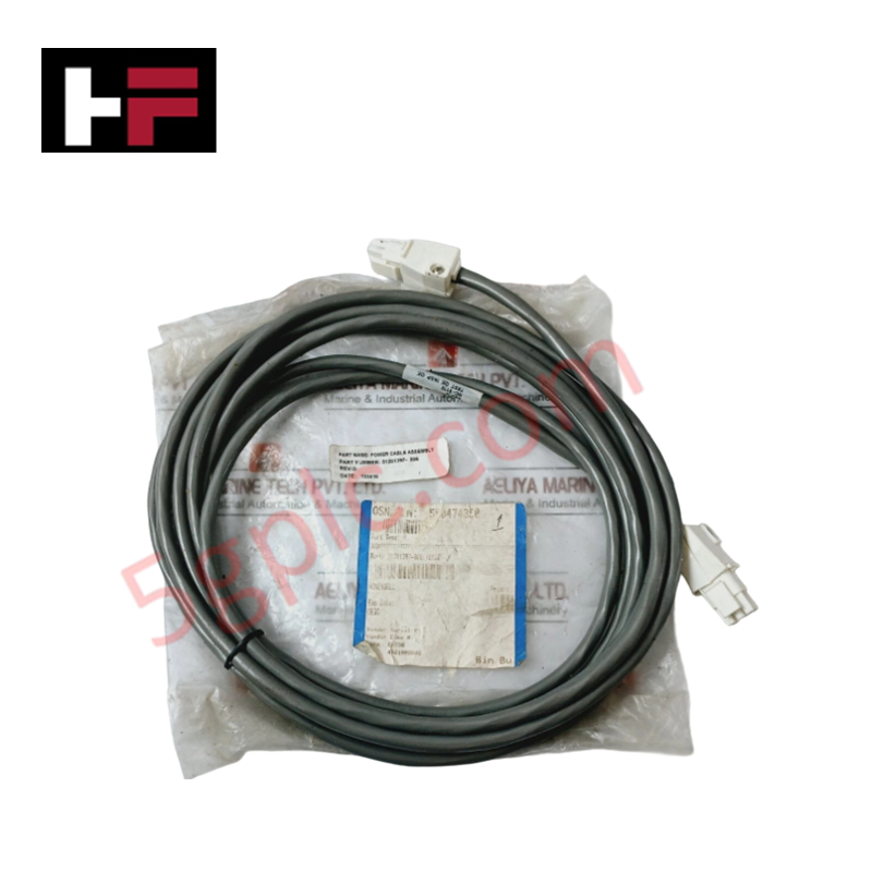
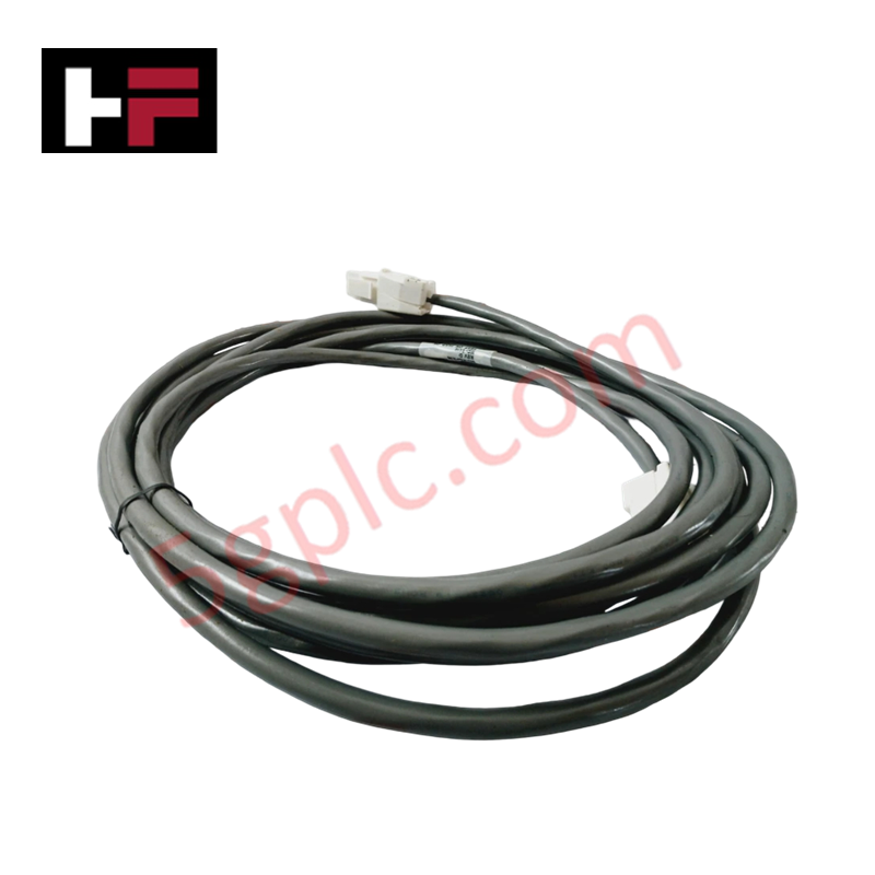
Configured for internal signal and power distribution in Honeywell Experion PKS platforms, the Honeywell 51204120-300 (51204120-300 Cable Assemblies) provides direct physical/electrical execution.
Hardware Specifications
| Parameter | Specification |
|---|---|
| Model | 51204120-300 |
| Brand | Honeywell |
| Origin | USA / Global Manufacturing |
| Weight | 0.35 kg |
| Dimensions | Standard System Cabinet Length |
| Operating Temp | -40 to +85 deg C |
| Power Consumption | Passive wiring component |
| Component Type | Internal System Cable Assembly |
| System Series | Experion PKS / Series C |
| Conductor Material | Annealed copper alloy |
| Shielding | High-coverage braided and foiled shield |
| Connector Type | Multi-pin factory-terminated connections |
| Insulation Material | Industrial flame-retardant PVC |
4-20 mA HART Loop Protocol and Channel-to-Channel Isolation
The 51204120-300 cable assembly serves as a primary signal link connecting field termination assemblies (FTAs) and I/O modules across system racks. By incorporating high-coverage overall shielding, the assembly suppresses continuous high-frequency electromagnetic interference, preserving low-amplitude signal dynamics used in 4-20 mA HART loop protocol communications.
The factory-molded multi-pin connector housings ensure low-resistance pin contact while preventing ground loops across cabinet backplates. This maintains channel-to-channel isolation specs required for precision analog input and output signal loops.
Frequently Asked Questions
Q: What is the primary operational purpose of the 51204120-300 cable?
A: The cable assembly provides internal point-to-point interconnectivity between Honeywell I/O modules, termination assemblies, and backplane distribution racks.
Q: What shielding mechanisms protect data transmission along the cable assembly?
A: The assembly incorporates a full-coverage shield braid and foil wrap to reject external electromagnetic and radio-frequency noise within industrial enclosures.
Q: Can the cable assembly be connected while the I/O rack is energized?
A: Connecting or disconnecting cable assemblies must only be performed after verifying loop power is isolated to prevent unexpected field circuit tripping.
Field Installation Guidelines
- Verify that the system chassis and adjacent I/O loops are de-energized prior to inserting or removing the cable connectors.
- Inspect connector pins and housing keyways for physical alignment before applying force to lock the connectors into position.
- Secure the cable along panel wireways using non-conductive cable ties, ensuring no mechanical tension is applied to the termination points.
- Ensure shield grounding straps or connector drain wires are firmly bonded to the cabinet protective earth (PE) bus.
Additional Information
- 100% Genuine Parts: All products are original and authentic, ensuring reliable industrial performance.
- 30-Day Refund Guarantee: Return any in-stock item within 30 days in original, unopened packaging for a full refund (excluding shipping and fees).
- 12-Month Warranty: Covers defects in materials or workmanship; excludes misuse, normal wear, or unauthorized modifications.
- Worldwide Shipping: We ship via USPS, UPS, FedEx, and DHL. Delivery times vary by country and may be subject to customs or import fees.
- Support & Contact: Technical and warranty assistance is available anytime. Contact us here: Contact.
- Purchase Guidance: Check product specifications and compatibility carefully before ordering to ensure proper application.


Tech & Buying Guide

Step-by-Step System Cabinet Health Check Guide for PLC and DCS Infrastructure

Top 5 Operational Advantages of HMIs in Modern Factory Automation
