










Product Details
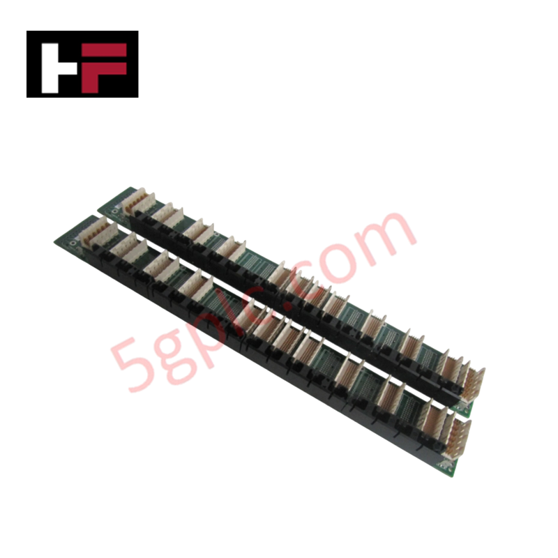
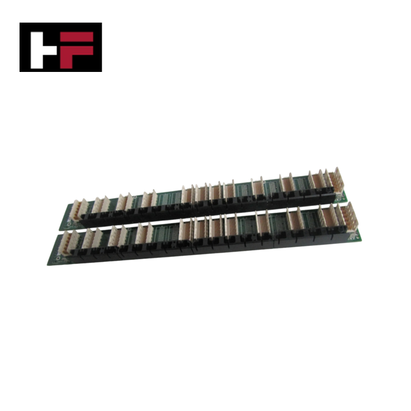
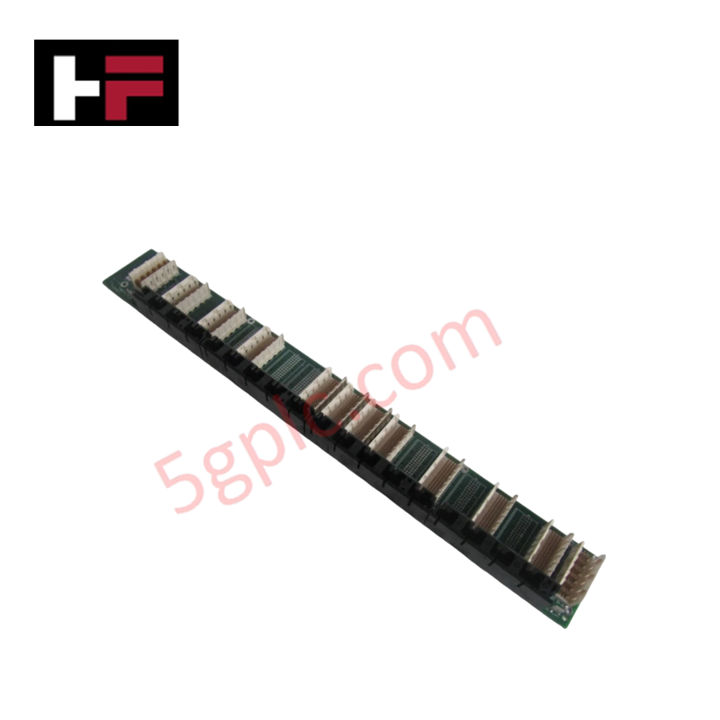
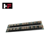
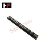
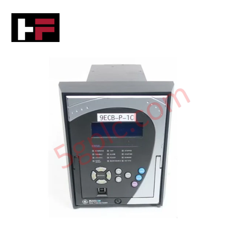
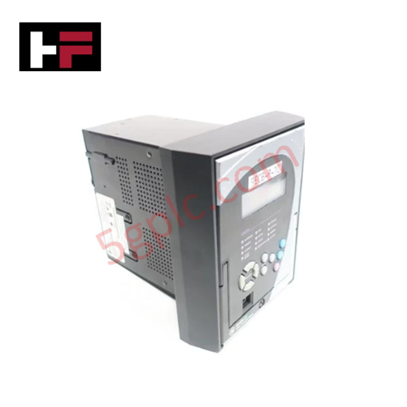
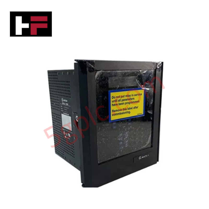
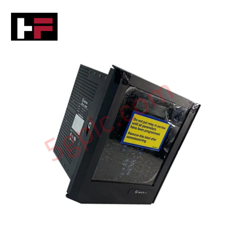
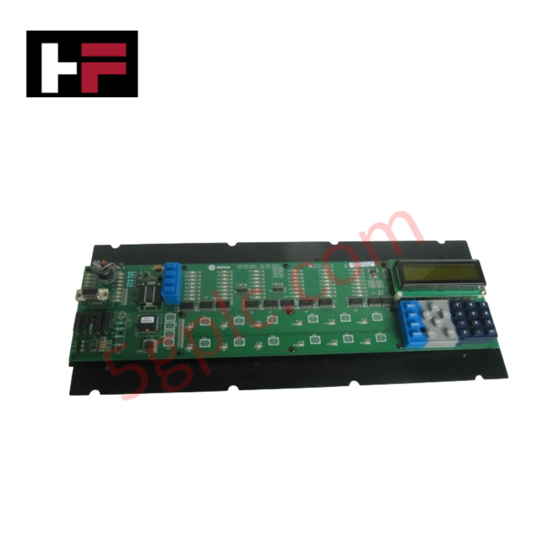
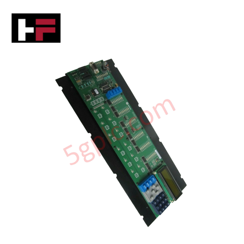
Configured for module-to-module inter-bus communication and internal power distribution in GE Multilin UR200 relay chassis, the GE 12A0-0102-A1 (12A0-0102 Bus Board PCB) provides direct physical/electrical execution.
Hardware Specifications
| Parameter | Specification |
|---|---|
| Model | 12A0-0102-A1 |
| Brand | GE / GE Multilin |
| Origin | USA |
| Dimensions | Standard Multilin UR200 Chassis Interconnect PCB |
| Operating Temp | -40 to +60 deg C |
| Power Consumption | Passive Backplane Interconnect / Internal Bus Powered |
| System Platform | GE Multilin UR Series / UR200 Relays |
| Board Type | Internal Bus Board Printed Circuit Board |
| Connector Type | Multi-pin High-Density Backplane Headers |
| Substrate | Industrial FR-4 Multilayer PCB |
Backplane Bus Communication Velocity and Firmware Flash Compatibility
The 12A0-0102-A1 bus board acts as the structural internal backplane for UR200 protection relays, routing parallel address, data, and diagnostic lines between CPU modules, I/O cards, and power supply units. By establishing fixed trace impedance and low-crosstalk signal routing, the assembly maintains deterministic backplane bus communication velocity across all populated card slots. The passive wiring matrix operates transparently to CPU software operations, preserving firmware flash compatibility across successive Multilin UR OS firmware updates and hardware card swaps.
Frequently Asked Questions
Q: How does the 12A0-0102-A1 board interface with inserted UR200 option modules?
A: Option cards slide directly along chassis guide rails to engage high-density edge connectors mounted on the front face of the 12A0-0102-A1 bus board.
Q: Is hot-swapping supported for modules connected through the 12A0-0102-A1 bus board?
A: Auxiliary control power to the UR200 chassis must be isolated prior to removing or inserting modules to prevent transient arcing across backplane power pins.
Field Installation Guidelines
- Disconnect all control power sources and isolate CT/PT secondary connections before opening the relay enclosure.
- Wear a grounded ESD wrist strap connected to the chassis ground terminal to prevent static discharge to the circuit trace matrix.
- Align the 12A0-0102-A1 bus board with the rear chassis mounting standoffs inside the empty UR200 rack enclosure.
- Fasten all board retention screws in an alternating pattern to eliminate mechanical stress across the solder joints.
- Inspect all backplane pin headers for pin alignment and freedom from debris prior to reinserting system cards.
Additional Information
- 100% Genuine Parts: All products are original and authentic, ensuring reliable industrial performance.
- 30-Day Refund Guarantee: Return any in-stock item within 30 days in original, unopened packaging for a full refund (excluding shipping and fees).
- 12-Month Warranty: Covers defects in materials or workmanship; excludes misuse, normal wear, or unauthorized modifications.
- Worldwide Shipping: We ship via USPS, UPS, FedEx, and DHL. Delivery times vary by country and may be subject to customs or import fees.
- Support & Contact: Technical and warranty assistance is available anytime. Contact us here: Contact.
- Purchase Guidance: Check product specifications and compatibility carefully before ordering to ensure proper application.


Tech & Buying Guide

Step-by-Step System Cabinet Health Check Guide for PLC and DCS Infrastructure

Top 5 Operational Advantages of HMIs in Modern Factory Automation
