










Product Details
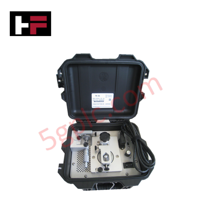
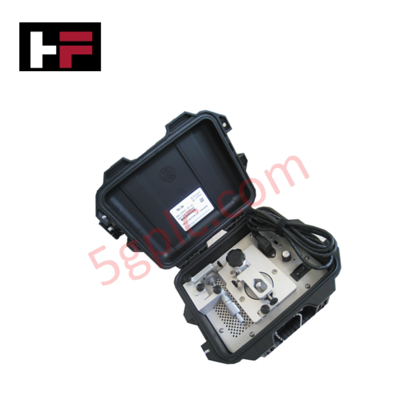
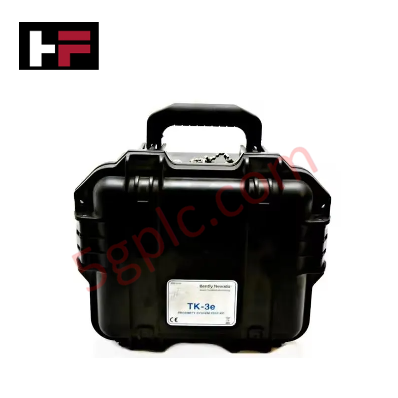
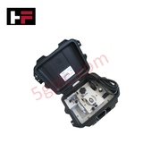
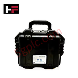
The Bently Nevada 177313-02-01, also cataloged as the 177313 Electric Driven TK-3e, operates as a dedicated hardware component for calibration and field verification of proximity transducers within Bently Nevada Machinery Monitoring Systems.
Suffix Breakdown & Model Matrix
| Option Field | Code | Configuration Detail |
|---|---|---|
| Scale Units Option | 02 | Metric calibration scale |
| Power Cord Type Option | 01 | American standard power cord |
Hardware Specifications
| Parameter | Specification |
|---|---|
| Model | 177313-02-01 |
| Brand | Bently Nevada |
| Origin | USA |
| Weight | 8 kg shipping weight |
| Dimensions | 19.5 cm x 29.9 cm x 24.8 cm (H x W x D) |
| Operating Temp | 0 deg C to 54 deg C (32 deg F to 130 deg F) |
| Power Consumption | Line-powered electric motor drive mechanism |
| Storage Temp | -18 deg C to 65 deg C (0 deg F to 150 deg F) |
| Environmental Protection | Designed to meet IP54 for dust and water exposure (closed) |
| Operating Humidity | 95% non-condensing humidity |
Transducer Calibration and Gap Voltage Validation
The 177313-02-01 electric-driven calibration instrument simulates mechanical shaft motion to verify eddy-current probe scaling and Proximitor sensor response across defined displacement ranges. Utilizing an electric motor-driven wobble plate assembly, the unit maintains mechanical alignment to test target displacement against probe output voltages. This calibration setup enables field verification of gap voltage targets (-10 VDC nominal setting) and linear scale factor calculations without disturbing installed rotor dynamic monitoring channels or dismantling machine bearing housings.
Frequently Asked Questions
Q: How does the metric scale unit option affect displacement measurements?
A: Option 02 equips the micrometer assembly with metric increments, providing direct mechanical displacement reference readings in millimeters during transducer calibration routines.
Q: What protection rating applies when the instrument enclosure is closed?
A: The closed housing assembly meets IP54 dust and splash water ingress protection standards for transport across field environments.
Field Installation Guidelines
- Position the instrument on a flat, stable surface within reach of an AC power outlet matching the option 01 American cord configuration.
- Inspect the micrometer spindle, target plate, and probe mounting adapter to confirm surfaces are free of debris or mechanical burrs.
- Secure the proximity probe into the probe holder, ensuring the sensor tip remains parallel to the target disc surface.
- Connect the proximity probe extension cable to its corresponding Proximitor sensor and establish multimeter connections across the DC voltage output terminals.
- Rotate the micrometer dial to verify physical gap zeroing before adjusting spindle displacement to validate probe linearity across the full operating range.
Additional Information
- 100% Genuine Parts: All products are original and authentic, ensuring reliable industrial performance.
- 30-Day Refund Guarantee: Return any in-stock item within 30 days in original, unopened packaging for a full refund (excluding shipping and fees).
- 12-Month Warranty: Covers defects in materials or workmanship; excludes misuse, normal wear, or unauthorized modifications.
- Worldwide Shipping: We ship via USPS, UPS, FedEx, and DHL. Delivery times vary by country and may be subject to customs or import fees.
- Support & Contact: Technical and warranty assistance is available anytime. Contact us here: Contact.
- Purchase Guidance: Check product specifications and compatibility carefully before ordering to ensure proper application.

Tech & Buying Guide

Why 24V DC Power Supplies Standardize Modern Industrial Automation
Industrial control cabinets worldwide rely on 24V DC as the universal power standard for field instrumentation, sensors, and controllers. Walk into any manufacturing plant, and you will find PLCs, human-machine interfaces (HMIs), and smart actuators running on extra-low voltage DC. Standardizing on 24V DC enhances operational safety, lowers cabinet footprint, and maintains steady control performance across factory networks.

Essential Motion Control Commands: A Practical Guide for Engineers
Automation engineers often rely on precise position and speed control to drive modern factory machinery. Modern industrial systems, such as Programmable Logic Controllers (PLCs) and Distributed Control Systems (DCS), depend heavily on standardized motion instructions. Mastering these commands ensures operational safety, protects mechanical components, and optimizes cycle times across production lines.
Mastering Modern Industrial Joystick Controls in Heavy Automation
Industrial joysticks play a pivotal role in human-machine interaction across heavy material handling and mobile hydraulics. These tactile controllers translate complex operator movements into precise electrical signals for PLCs, motion controllers, and DCS networks. Consequently, selecting and installing the right joystick architecture ensures operator safety, reduces fatigue, and optimizes equipment performance.