










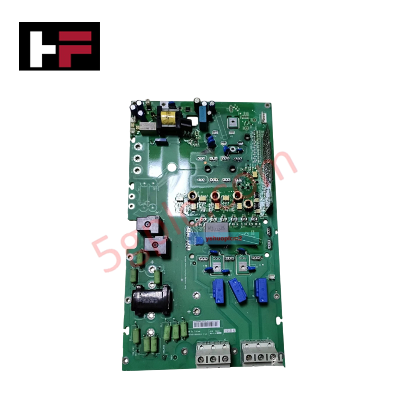


Product Details
Configured for industrial automation and motor control in ACS800 series frequency converters, the ABB RINT-6411C (RINT-6411C Drive Control Board) provides direct physical/electrical execution.
Hardware Specifications
| Parameter | Specification |
|---|---|
| Model | RINT-6411C |
| Brand | ABB |
| Origin | Finland |
| Weight | 0.32 kg |
| Dimensions | 115 mm x 75 mm x 25 mm |
| Operating Temp | 0 to +50 deg C (Standard operational baseline) |
| Power Consumption | Internally derived from inverter bus supply |
| Product Type | Drive Control Boards |
| Application | Motor gate driver and interface circuit routing |
| Mounting | DIN rail |
Profinet / EtherNet/IP Deterministic Networks and Driver Synchronization
The electrical layout of the RINT-6411C routes internal gating commands directly to the main inverter power semiconductors while maintaining real-time parity with the host processor board. This data path manages gate switching states synchronously with master parameters, protecting backplane bus communication velocity and preventing instruction drift when integrated with Profinet / EtherNet/IP deterministic networks. The layout preserves strict firmware flash compatibility across standard ACS800 control units, ensuring localized pulse-width modulation processing does not alter host timing constraints or decrease external I/O density scaling options.
Frequently Asked Questions
Q: Does the RINT-6411C support direct hot-swap physical replacement while the main DC bus is charged?
A: No. The board operates in direct electrical connection with high-voltage inverter circuits. The entire drive unit must be powered down, and the DC bus capacitors must be fully discharged before executing maintenance or physical board extraction.
Q: How is configuration data or firmware flash compatibility verified for this replacement unit?
A: The RINT-6411C functions primarily as an interface and gating distribution layer. It synchronizes with the main drive application program automatically upon power-up, provided that hardware jumper profiles on the board match the factory specifications of the host frame size.
Q: What mechanisms protect the communication path from high-frequency electromagnetic noise?
A: The internal logic layout implements differential signal pathways and dedicated filtering capacitors to isolate logic processing matrices from the high dv/dt switching transients generated by adjacent IGBT modules.
Field Installation Guidelines
- DIN Rail Alignment: Mount the board securely to the internal cabinet 35 mm DIN rail. Ensure the structural locking clips engage fully to suppress physical displacement from motor-induced mechanical vibration.
- Ribbon Cable Seating: Connect the parallel multi-pin ribbon cables to the primary processor assembly. Verify that all locking tabs click into place to prevent intermittent data drops during thermal expansion cycles.
- Low-Impedance Bonding: Ensure the DIN rail mounting pathway links directly to the common structural inverter ground plate. A clean metal-to-metal contact is required to sink common-mode noise away from the gate driver channels.
- Clearance and Airflow: Maintain the specified 25 mm depth profile clearance boundaries free from obstruction to enable unimpeded convective airflow from the main chassis cooling fans.
Additional Information
- 100% Genuine Parts: All products are original and authentic, ensuring reliable industrial performance.
- 30-Day Refund Guarantee: Return any in-stock item within 30 days in original, unopened packaging for a full refund (excluding shipping and fees).
- 12-Month Warranty: Covers defects in materials or workmanship; excludes misuse, normal wear, or unauthorized modifications.
- Worldwide Shipping: We ship via USPS, UPS, FedEx, and DHL. Delivery times vary by country and may be subject to customs or import fees.
- Support & Contact: Technical and warranty assistance is available anytime. Contact us here: Contact.
- Purchase Guidance: Check product specifications and compatibility carefully before ordering to ensure proper application.


Tech & Buying Guide

Understanding VFD Mechanical Brake Logic and Control in Industrial Automation
Variable Frequency Drives (VFDs) play a crucial role in modern industrial automation by controlling motor speed, torque, and acceleration. However, high-inertia loads and vertical lifting systems require precise mechanical braking logic to ensure operational safety and prevent equipment damage.

Why Programmable Logic Controllers Drop into Stop Mode: An Expert Analysis
Industrial automation systems rely heavily on Programmable Logic Controllers (PLCs) to maintain uninterrupted production. When a PLC unexpectedly shifts from Run to Stop mode, whole manufacturing lines stall.
As control systems evolve across modern factory automation, understanding the root causes of these interruptions helps engineers minimize costly downtime. This technical guide breaks down why PLCs trip into Stop mode and provides practical strategies to mitigate system faults.

Understanding Root Causes of Unplanned PLC Stop Mode in Industrial Automation
Modern Programmable Logic Controllers manage execution through distinct operational states: Run, Stop, Start-Up, and Hold. During power-up, a controller initializes memory registers within Stop mode before briefly transitioning to Start-Up mode. During this phase, internal self-diagnostics evaluate system integrity across hardware and user programs. If the controller detects no critical faults, it enters Run mode to execute the control program continuously. However, any severe system anomaly forces the CPU back into Stop mode immediately to prevent erratic machine behavior across the plant floor.