











Product Details
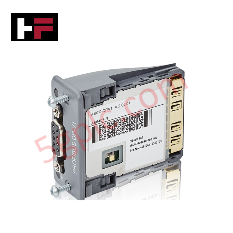
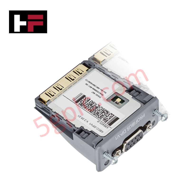
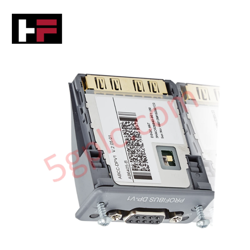
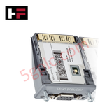
Configured for Profibus communication interfacing in IRC5 controller platforms, the ABB DSQC 667 (3HAC026840-001 Profibus Board) provides direct physical signal processing for fieldbus integration.
Hardware Specifications
| Parameter | Specification |
|---|---|
| Model | DSQC 667 |
| Brand | ABB |
| Part Number | 3HAC026840-001 |
| Origin | Sweden |
| Weight | 0.028 kg |
| Dimensions | 50.5 mm x 22.3 mm x 56.5 mm |
| Operating Temp | Standard industrial ambient |
| Power Consumption | System backplane dependent |
| Interface Type | Profibus |
Profinet / EtherNet/IP deterministic networks
The DSQC 667 acts as the communication interface layer for the controller, enabling deterministic data exchange between the robot controller and connected Profibus DP field devices. The hardware utilizes standardized bus signaling to ensure frame synchronization and data integrity across the network segment. Firmware flash compatibility is determined by the installed RobotWare version; users must confirm that the system software supports the specific GSD file requirements of the board. The board operates within the deterministic constraints of the fieldbus, requiring accurate baud rate configuration and proper bus termination to maintain stable communication cycles.
Frequently Asked Questions
Q: Can the DSQC 667 be hot-swapped while the IRC5 controller is powered?
A: No. The board must be installed or removed only when the control system is de-energized to prevent damage to the backplane communication pins and internal logic circuits.
Q: What is the primary cause of cyclic data communication errors with this board?
A: Communication errors typically result from incorrect GSD file integration, impedance mismatches in the Profibus cable, or missing termination resistors at the ends of the bus segment.
Field Installation Guidelines
- ESD Protection: Utilize an antistatic wrist strap and maintain a clean work environment during installation to prevent electrostatic discharge from damaging the board circuitry.
- Mechanical Seating: Insert the board into the designated slot on the communication backplane. Verify that the locking mechanism is fully engaged to prevent vibration-induced disconnections.
- Bus Termination: Install a 220 ohm termination resistor at both physical ends of the Profibus cable to prevent signal reflections that induce data frame corruption.
- Cable Shielding: Ensure that the Profibus cable shield is connected to the common ground at the controller entry point to minimize noise ingress and maintain signal-to-noise ratio.
- Baud Rate Matching: Confirm that the network baud rate configuration in the controller software aligns precisely with the parameters of the slave nodes to prevent "bus-off" diagnostic conditions.
Additional Information
- 100% Genuine Parts: All products are original and authentic, ensuring reliable industrial performance.
- 30-Day Refund Guarantee: Return any in-stock item within 30 days in original, unopened packaging for a full refund (excluding shipping and fees).
- 12-Month Warranty: Covers defects in materials or workmanship; excludes misuse, normal wear, or unauthorized modifications.
- Worldwide Shipping: We ship via USPS, UPS, FedEx, and DHL. Delivery times vary by country and may be subject to customs or import fees.
- Support & Contact: Technical and warranty assistance is available anytime. Contact us here: Contact.
- Purchase Guidance: Check product specifications and compatibility carefully before ordering to ensure proper application.




Tech & Buying Guide

Wellhead Control Panel (WHCP) Architecture in Oil and Gas Automation
Upstream oil and gas operations rely on specialized field control platforms to manage wellhead extraction safety and hydraulic actuation. A Wellhead Control Panel (WHCP) serves as a dedicated hydraulic and pneumatic power unit designed to operate critical Christmas Tree isolation valves. By interfacing field safety components directly with Programmable Logic Controller (PLC) architecture, a WHCP protects upstream extraction assets against overpressure, catastrophic leaks, and thermal emergencies.

Understanding Marshalling Cabinets in Industrial Control Systems Architecture
Industrial control system deployments rely on structured signal distribution to bridge field instrumentation with central processing hardware. A marshalling cabinet serves as the vital intermediate connection point between heavy field home-run multi-pair cables and delicate input/output (I/O) modules housed inside Programmable Logic Controller (PLC) or Distributed Control System (DCS) enclosures. By segregating field cable terminations from control hardware, engineers maintain system flexibility, safeguard controller components, and streamline commissioning workflows.

FAT vs SAT in Industrial Control Systems: Key Differences and Execution Guide
Industrial control system deployment relies on strict verification protocols to guarantee operational safety, system stability, and regulatory compliance. Commissioning complex Programmable Logic Controller (PLC) racks, Distributed Control Systems (DCS), and Safety Instrumented Systems (SIS) requires two critical milestones: the Factory Acceptance Test (FAT) and the Site Acceptance Test (SAT). Both procedures validate that system automation meets design specifications, but they occur at different stages of project execution and target distinct operational risks.