










Product Details
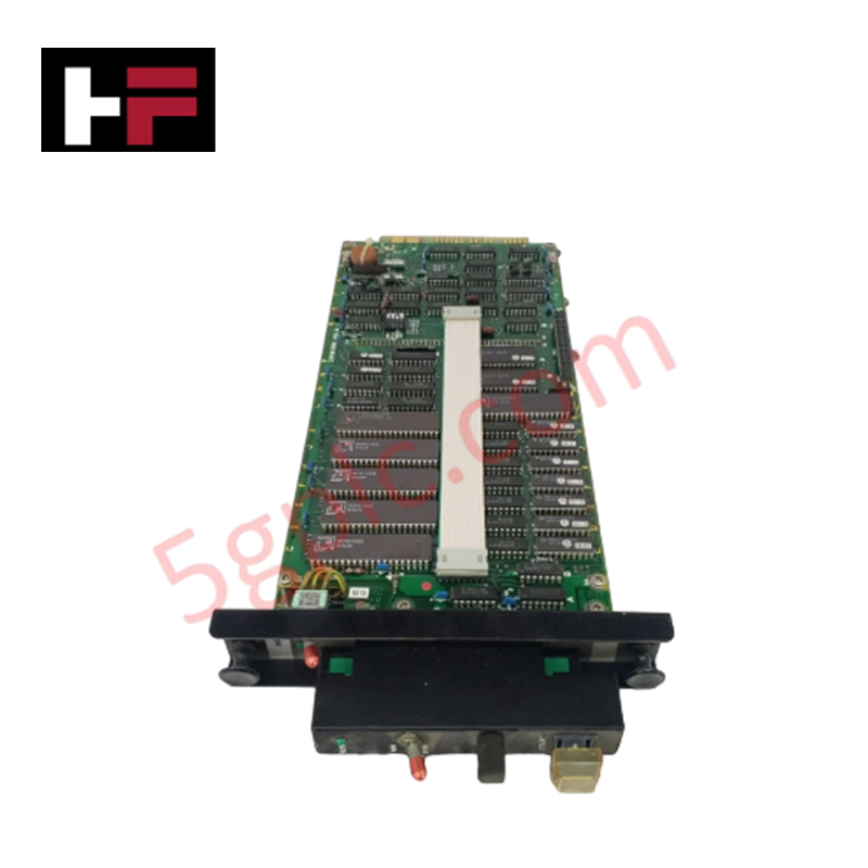
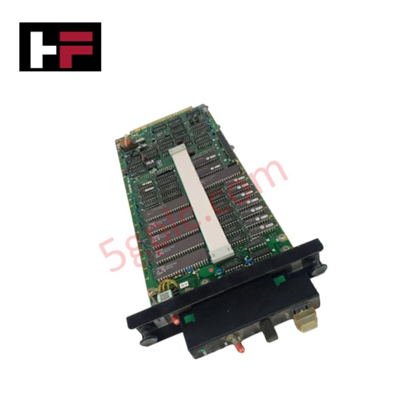
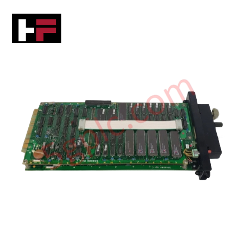
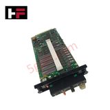
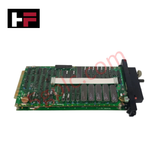
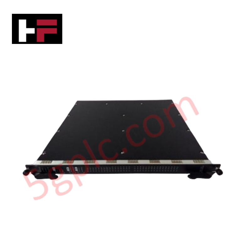
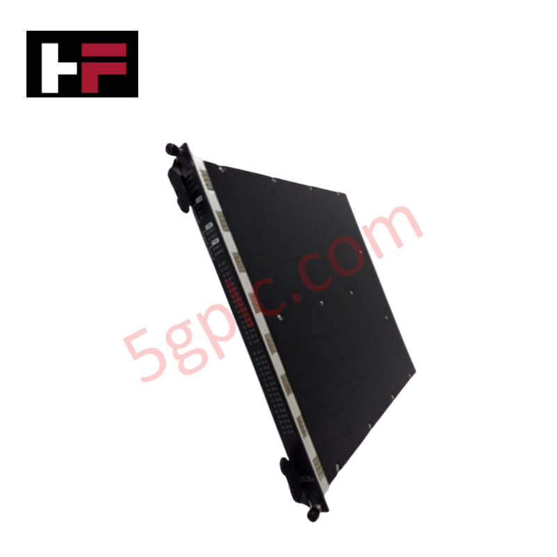
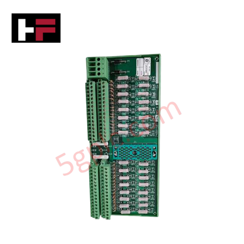
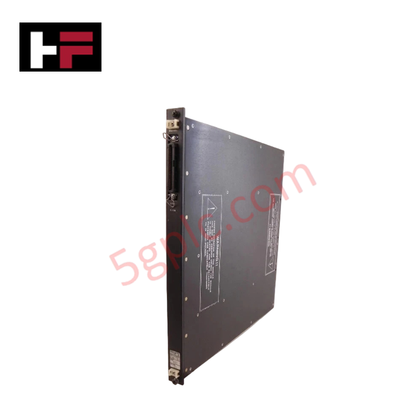
The Yokogawa NP1*C, also cataloged as the NP1 Input/Output Module, operates as a dedicated hardware component for field signal processing and system interface execution within Yokogawa PLC platforms. The module interfaces analog and digital field signals with controller memory over system backplane connections, utilizing 512 KB to 4 MB RAM and 256 KB to 2 MB Flash ROM for onboard data buffering and program storage. Communication lines support RS-232, RS-485, and Ethernet physical layers to execute program control logic written in ladder logic, function block, or structured text.
Suffix Breakdown & Model Matrix
| Code Element | Specification / Description |
|---|---|
| NP1 | Base model designation for PLC modular processor and I/O series |
| *C | Style code Revision C indicating hardware revision and internal circuit design |
Hardware Specifications
| Parameter | Specification |
|---|---|
| Model | NP1*C |
| Brand | Yokogawa |
| Origin | Japan |
| Weight | 0.2 kg |
| Dimensions | 100 mm x 100 mm x 50 mm |
| Operating Temp | -25 deg C to 70 deg C |
| Power Consumption | 24 VDC / backplane bus powered |
| Memory Capacity | 512 KB to 4 MB RAM, 256 KB to 2 MB Flash ROM |
| Communication Interfaces | RS-232, RS-485, Ethernet |
| Supported Languages | Ladder logic, function block, structured text |
| I/O Configuration | Modular (analog and digital options) |
Channel Isolation and DCS Process Integration
The NP1*C module processes 4-20 mA HART loop protocol parameters alongside discrete digital field inputs. To maintain signal accuracy across mixed instrument loops, channel-to-channel isolation circuits suppress electrical cross-talk and ground loop currents between field wiring and internal processing buses. Thermal input channels incorporate cold junction compensation (CJC) processing to ensure precise temperature signal conversion. Fieldbus data received over RS-485 or Ethernet networks are mapped directly into system memory, ensuring real-time execution of function block control routines without bus contention.
Frequently Asked Questions
Q: How does the module handle programming logic execution and memory allocation?
A: Control program routines written in ladder logic, function block, or structured text reside in the 256 KB to 2 MB Flash ROM. Active process variables and scan cycle runtime data are stored within the 512 KB to 4 MB RAM space.
Q: What grounding and shielding methods protect serial communication over RS-485 lines?
A: RS-485 network cables require shielded twisted-pair conductors with the shield braid bonded directly to the cabinet functional earth bus bar at a single termination point to prevent noise coupling.
Q: Is hot-swapping supported for the NP1*C module on active PLC subracks?
A: Hot-swapping depends on the specific baseplate slot configuration; power down the local slot or subrack prior to module extraction unless redundant backplane power and bus isolation are active.
Field Installation Guidelines
- Rack Mounting: Align the NP1*C module with the guide rails in the designated PLC slot. Push firmly until the backplane connectors latch into place, and tighten retaining screws to secure the chassis against mechanical vibration.
- Wiring Separation: Route low-voltage RS-232, RS-485, and Ethernet communication cables in separate wire channels from high-voltage AC power lines to prevent electromagnetic interference.
- Grounding: Connect the main rack assembly to a low-impedance earth ground plane. Cable shields for serial and Ethernet connections must terminate at designated grounding lugs.
- Thermal Management: Maintain clear air ventilation channels above and below the module housing (100 mm x 100 mm x 50 mm) to ensure natural convection keeps the operating ambient temperature between -25 deg C and 70 deg C.
Additional Information
- 100% Genuine Parts: All products are original and authentic, ensuring reliable industrial performance.
- 30-Day Refund Guarantee: Return any in-stock item within 30 days in original, unopened packaging for a full refund (excluding shipping and fees).
- 12-Month Warranty: Covers defects in materials or workmanship; excludes misuse, normal wear, or unauthorized modifications.
- Worldwide Shipping: We ship via USPS, UPS, FedEx, and DHL. Delivery times vary by country and may be subject to customs or import fees.
- Support & Contact: Technical and warranty assistance is available anytime. Contact us here: Contact.
- Purchase Guidance: Check product specifications and compatibility carefully before ordering to ensure proper application.





Tech & Buying Guide

Understanding Safety Relays in Industrial Automation: Architecture, Operation, and Functional Safety
Standard electromechanical relays provide basic electrical isolation between low-voltage control circuits and high-power output loads. A traditional switching relay features a magnetic coil driving mechanical Common (COM), Normally-Open (NO), and Normally-Closed (NC) contacts. However, standard relays pose severe functional risks when deployed in critical safety interlock circuits. High current inrush or mechanical wear can weld contacts together permanently. If contact welding occurs in an emergency stop circuit, pressing the button fails to halt hazardous machinery movements. Consequently, global functional safety standards prohibit standard relays for critical machine guarding functions.

Mastering Wire Identification in Industrial Automation: The Power of Ferrules and Cross-Ferruling
Proper wire labeling forms the cornerstone of reliable control system installation and long-term maintenance. In complex industrial automation environments, technicians terminate thousands of conductor ends inside control panels, marshalling racks, and field junction boxes. Ferrules serve as individual tube-shaped sleeve markers slipped onto conductors before final termination. While technicians historically relied on pre-printed individual letter rings, modern control panel builders utilize automated ferrule printing machines. These thermal-transfer printers generate durable, single-sleeve heat-shrink tags directly matching approved wiring schematics, significantly accelerating cabinet assembly workflows.

Understanding Marshalling Cabinets in Industrial Automation and Control Systems
Marshalling cabinets serve as the crucial connection hub between field instruments and centralized processing units. In large DCS and PLC control system architectures, hundreds of multipair field cables run from local junction boxes to the central instrument equipment room. The marshalling cabinet houses field terminal blocks, surge arresters, intrinsic safety isolation barriers, and interposing relays. By segregating field field-wiring terminations from sensitive processor hardware, engineers protect expensive controller backplanes from high-voltage transients. Consequently, this modular separation dramatically streamlines maintenance workflows and simplifies system expansion.