










Product Details
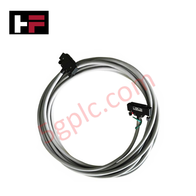
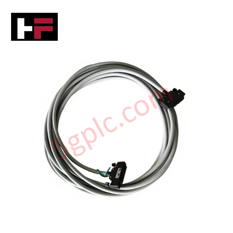
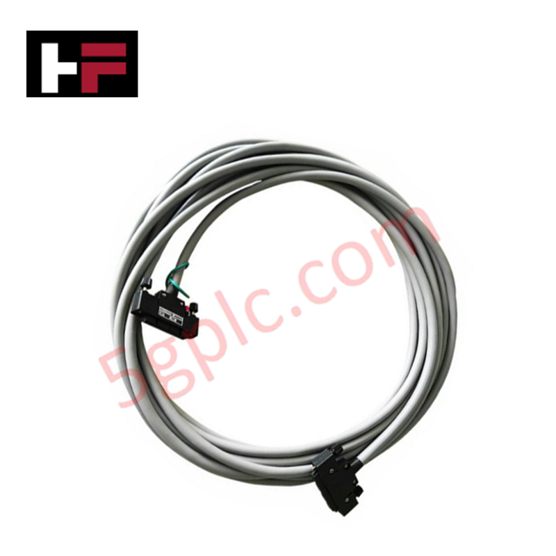
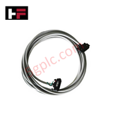
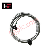
The Yokogawa KS9-10*B, also cataloged as the KS9 Signal Cable (50-50 pins), operates as a dedicated hardware component for multi-channel analog and digital I/O signal routing within Yokogawa CENTUM DCS terminal board architectures.
Suffix Breakdown & Model Matrix
| Code Element | Specification / Description |
|---|---|
| KS9 | Base signal cable model designation for 50-pin to 50-pin interface termination |
| -10 | Cable assembly length rating specifying 10 m total span |
| *B | Style code Revision B specifying connector shell design and mechanical strain relief |
Hardware Specifications
| Parameter | Specification |
|---|---|
| Model | KS9-10*B |
| Brand | Yokogawa |
| Origin | Japan |
| Weight | 3 kg |
| Dimensions | Cable length 10 m (50-pin to 50-pin termination) |
| Operating Temp | -20 deg C to 60 deg C |
| Power Consumption | Passive device (0 W) |
| Connector Type | 50-pin male to 50-pin male multi-pole connector |
| Conductor Gauge | AWG 24 stranded copper wire |
| Pin Configuration | 1-to-1 direct pinout mapping (50 pins to 50 pins) |
| Voltage Rating | 30 VDC maximum continuous |
| Current Rating | 1 A per conductor pin |
| Insulation Resistance | 100 Mohm minimum at 500 VDC |
| Shielding Structure | Overall aluminum-mylar foil with braided tinned copper shield and drain wire |
Channel Isolation and 4-20 mA HART Loop Signal Preservation
The KS9-10*B cable assembly maintains signal integrity for high-density analog 4-20 mA HART loop communication and digital discrete field channels. Individual conductor pairs inside the 10 m cable jacket feature precise twisted-pair geometry to mitigate cross-talk and magnetic induction between adjacent I/O channels. Designed to operate with channel-to-channel isolated I/O modules, the overall foil and braided shield configuration routes high-frequency electrical noise to chassis ground, ensuring zero degradation of superimposed HART digital frequency-shift keying (FSK) signals across the entire 10 m transmission path.
Frequently Asked Questions
Q: What is the maximum signal degradation or resistance expected over the 10 m length of the KS9-10*B cable?
A: The conductor resistance is rated below 0.09 ohm per meter at 20 deg C, resulting in a total loop resistance under 1.8 ohm for a 10 m run. This voltage drop is negligible for standard 4-20 mA current loop instruments and 24 VDC digital input channels.
Q: Can the KS9-10*B cable be disconnected or reconnected while field I/O channels are powered?
A: Hot-swapping the cable while field loops are energized is permissible under low-voltage conditions (30 VDC or less), provided connected DCS I/O modules support live terminal removal. However, disconnecting multi-channel cables de-energizes all 50 pin assignments simultaneously, disrupting active field control loops.
Q: How is shield continuity maintained between the 50-pin connectors?
A: Shield continuity is routed through dedicated grounded connector shell contacts and drain wires embedded at both ends, allowing direct grounding to the DCS rack backplane frame upon mating.
Field Installation Guidelines
- Cable Bend Radius: Maintain a minimum static bend radius of 80 mm and a dynamic bend radius of 120 mm during installation to prevent internal conductor strain or shield separation.
- Connector Mating and Fastening: Align the 50-pin connector keyways straight before insertion. Hand-tighten all mechanical retaining screws to ensure solid contact pressure and prevent connector detachment under vibration.
- Cable Routing and Separation: Route the signal cable through standard wire ducts, maintaining a minimum physical clearance of 300 mm from high-voltage AC power lines, variable frequency drive outputs, and heavy inductive loads to prevent electromagnetic interference.
- Grounding Protocol: Connect the cable drain wire directly to the functional earth (FE) bus bar at one end (DCS side) to avoid circulating ground loop currents.
Additional Information
- 100% Genuine Parts: All products are original and authentic, ensuring reliable industrial performance.
- 30-Day Refund Guarantee: Return any in-stock item within 30 days in original, unopened packaging for a full refund (excluding shipping and fees).
- 12-Month Warranty: Covers defects in materials or workmanship; excludes misuse, normal wear, or unauthorized modifications.
- Worldwide Shipping: We ship via USPS, UPS, FedEx, and DHL. Delivery times vary by country and may be subject to customs or import fees.
- Support & Contact: Technical and warranty assistance is available anytime. Contact us here: Contact.
- Purchase Guidance: Check product specifications and compatibility carefully before ordering to ensure proper application.




Tech & Buying Guide

Understanding Marshalling Cabinets in Industrial Automation and Control Systems
Marshalling cabinets serve as the crucial connection hub between field instruments and centralized processing units. In large DCS and PLC control system architectures, hundreds of multipair field cables run from local junction boxes to the central instrument equipment room. The marshalling cabinet houses field terminal blocks, surge arresters, intrinsic safety isolation barriers, and interposing relays. By segregating field field-wiring terminations from sensitive processor hardware, engineers protect expensive controller backplanes from high-voltage transients. Consequently, this modular separation dramatically streamlines maintenance workflows and simplifies system expansion.

Essential Best Practices for PLC Wiring and Installation in Industrial Automation
Successful control system deployment begins with thoroughly reviewing manufacturer technical documentation. Controllers from major brands like Allen-Bradley, Siemens, and Schneider Electric feature unique terminal layouts. Engineers must verify voltage requirements before connecting power cables to prevent catastrophic equipment damage. Standard line connections require strict adherence to regional electrical codes and proper wire color coding. Furthermore, panel builders should always establish a robust low-impedance ground connection using at least 16-AWG copper conductor tied directly to the main plant grounding grid.

Demystifying Programmable Logic Controllers: Comprehensive Guide to PLC Classification and Selection in Industrial Automation
Modern industrial automation heavily relies on Programmable Logic Controllers (PLCs) to drive factory floor efficiency. Over my 15 years as an industrial automation expert working with DCS, TSI, and control systems, I have seen PLCs evolve into the central nervous system of modern manufacturing. Selecting the right controller requires a deep understanding of PLC types based on physical size, hardware architecture, and power supply configurations.