








Product Details
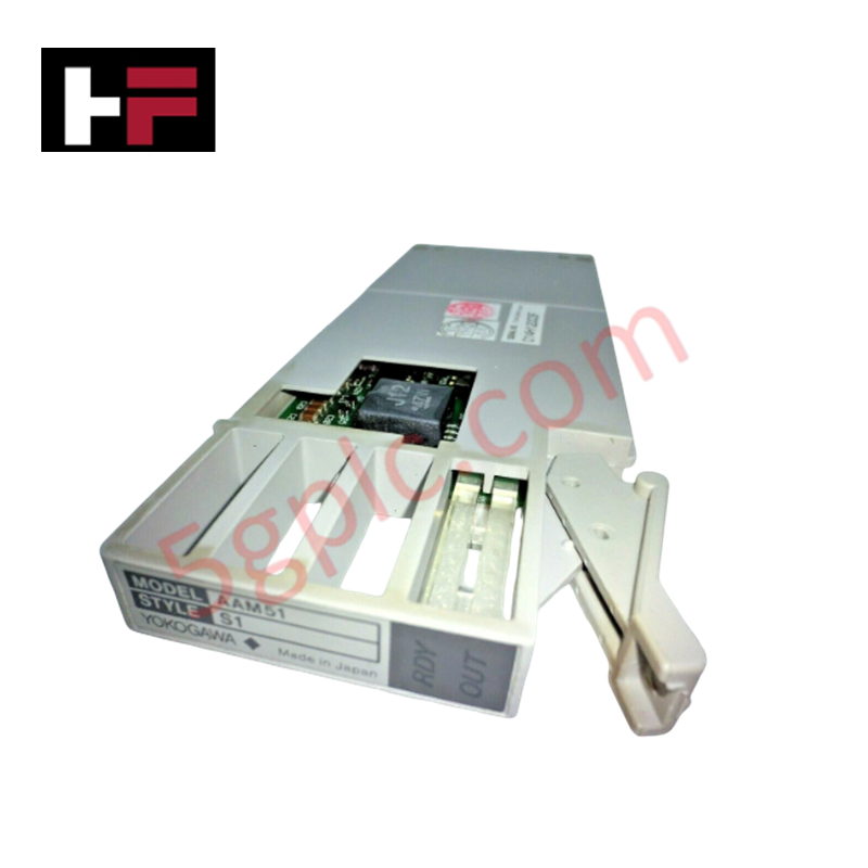
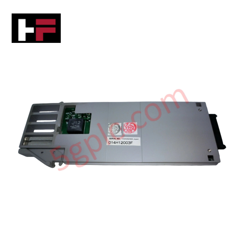
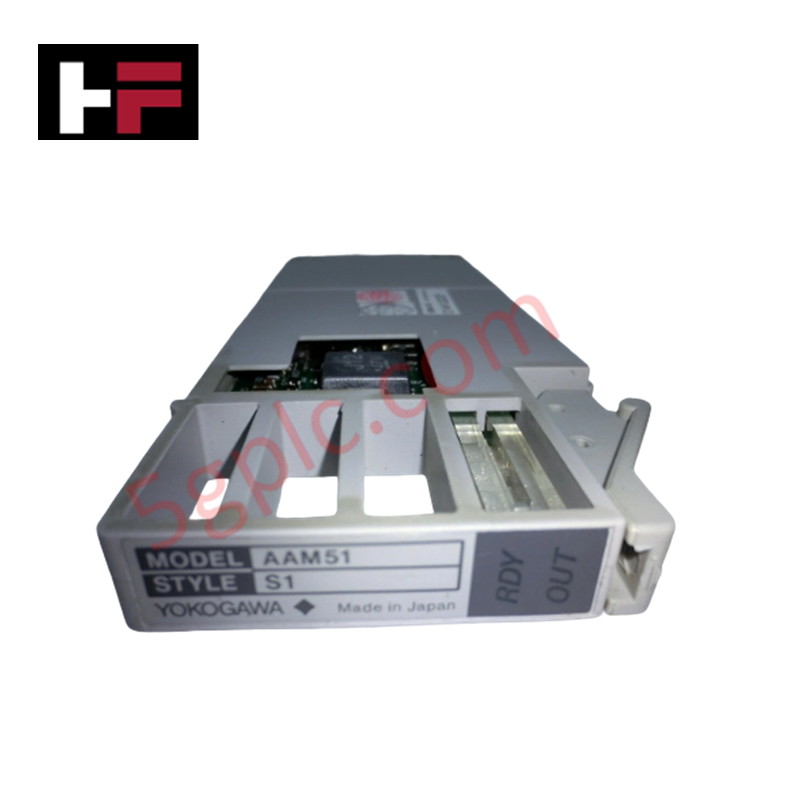
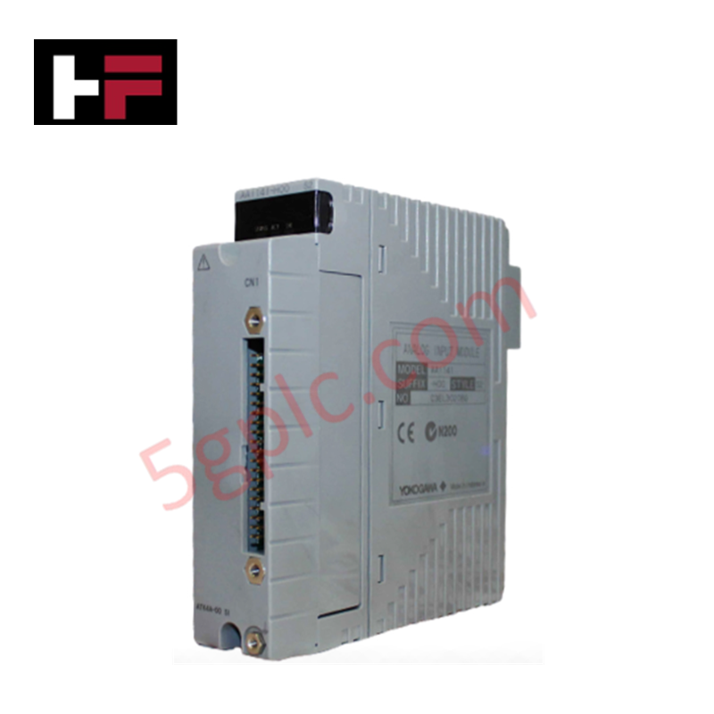
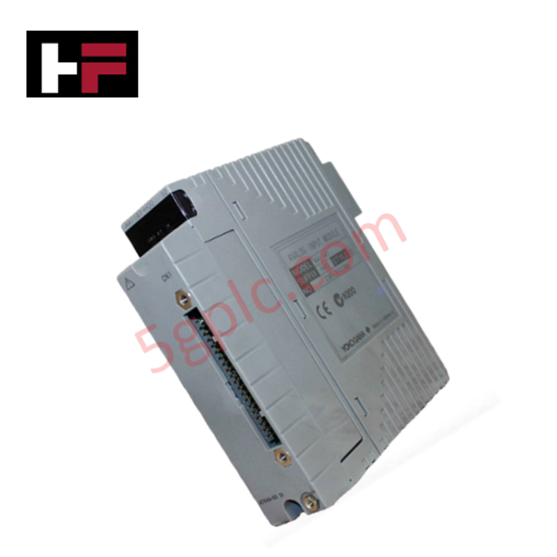
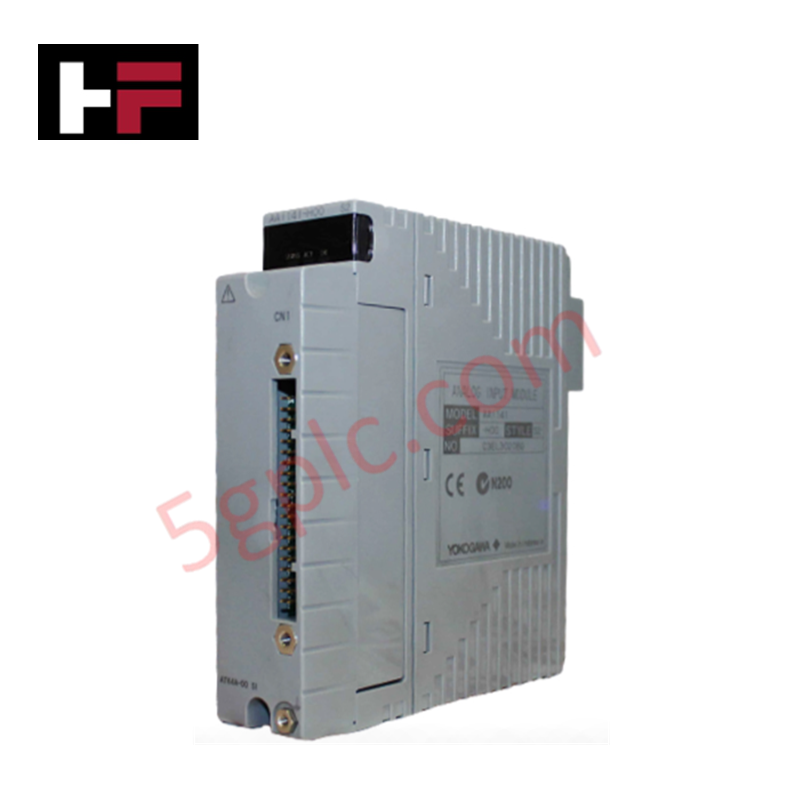
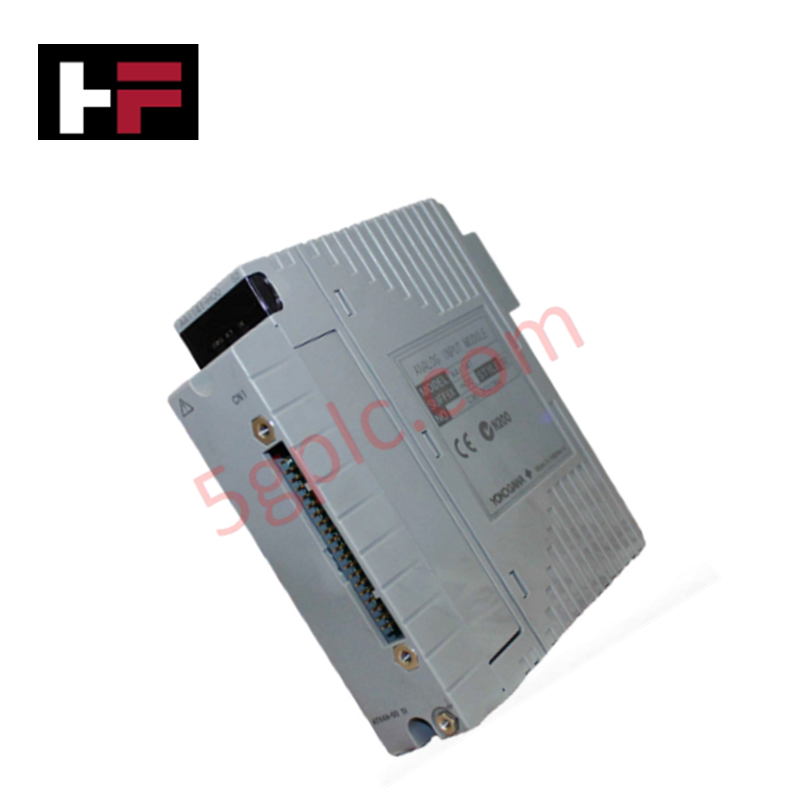
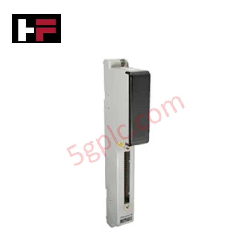
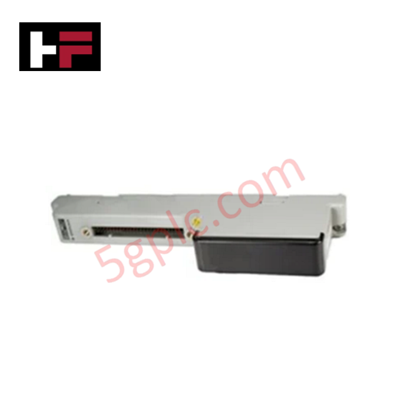
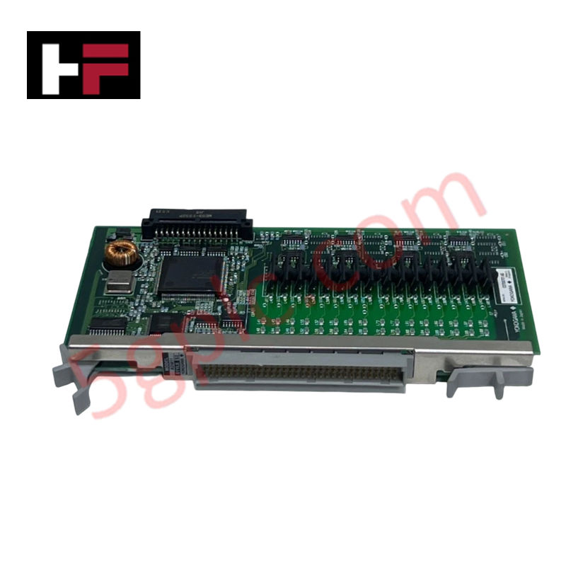
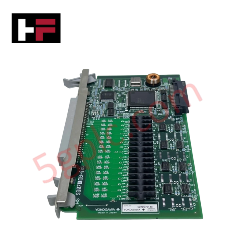
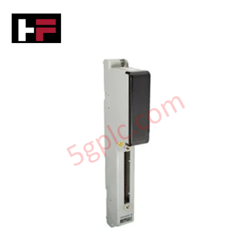
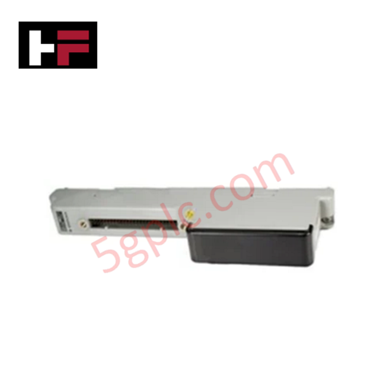
The YOKOGAWA AAM51 S1, also cataloged as the AAM51 Current/Voltage Output Module, operates as a dedicated hardware component for direct process output driving of valves and actuators within YOKOGAWA CENTUM system networks.
Hardware Specifications
| Parameter | Specification |
|---|---|
| Model | AAM51 S1 |
| Brand | YOKOGAWA |
| Origin | Japan |
| Weight | 1.5 kg |
| Dimensions | 2.2 cm x 12.4 cm x 12.6 cm |
| Operating Temp | Not Specified |
| Power Consumption | 38 mA or lower (24.0 VDC), 10 mA or lower (5.0 VDC) |
| Rated Output Range | 4 to 20 mA DC |
| Output Voltage Limit | 25.5 VDC or lower |
| Data Update Period | 2 ms or 22 ms (for step response) |
| Dielectric Withstanding Voltage | 1500 VAC for 1 minute; 42 VDC field-to-system |
| Mounting | Mounted on the nest for I/O adaptor (A2BA3D) |
4-20 mA HART Loop Protocol and Field Signal Interfacing
The AAM51 S1 generates software-configurable 4 to 20 mA DC current signals to drive final control elements such as control valves and positioners across process control loops. The card provides galvanic signal isolation rated at 1500 VAC for 1 minute and 42 VDC between field circuits and system backplane logic, suppressing ground loop currents and common-mode noise propagation. Signal routing operates in conjunction with standard 4-20 mA HART loop protocol field devices across CENTUM node nests.
Frequently Asked Questions
Q: What is the current consumption rating of the AAM51 S1 module?
A: The module consumes 38 mA or lower from the 24.0 VDC supply rail and 10 mA or lower from the 5.0 VDC backplane logic rail.
Q: How is the AAM51 S1 output module physically mounted in the system?
A: The module mounts directly onto an A2BA3D I/O adaptor nest for backplane inter-module connectivity.
Q: What response time configuration options are available for the output signal update?
A: The data update period can be configured to 2 ms or 22 ms depending on system step response requirements.
Field Installation Guidelines
Power down the I/O adaptor nest before installing or removing the AAM51 S1 module. Observe static safety measures by wearing a grounded ESD wrist strap while handling the unit. Align the card with the mounting slots on the A2BA3D I/O adaptor nest and press firmly until backplane connectors seat completely, then fasten retaining hardware to establish solid frame grounding. Ensure output cabling for 4 to 20 mA DC loops uses shielded twisted-pair cables, bonding the shield at a single earth termination point inside the control cabinet. Route signal lines separately from high-voltage AC power conductors.
Additional Information
- 100% Genuine Parts: All products are original and authentic, ensuring reliable industrial performance.
- 30-Day Refund Guarantee: Return any in-stock item within 30 days in original, unopened packaging for a full refund (excluding shipping and fees).
- 12-Month Warranty: Covers defects in materials or workmanship; excludes misuse, normal wear, or unauthorized modifications.
- Worldwide Shipping: We ship via USPS, UPS, FedEx, and DHL. Delivery times vary by country and may be subject to customs or import fees.
- Support & Contact: Technical and warranty assistance is available anytime. Contact us here: Contact.
- Purchase Guidance: Check product specifications and compatibility carefully before ordering to ensure proper application.
Tech & Buying Guide

Evaluating Industrial Automation: Architectural Benefits and Operational Challenges
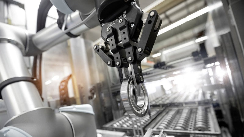
Modern manufacturing relies heavily on advanced industrial automation to streamline production cycles and maintain precise process execution. Automated control systems, programmable logic controllers (PLCs), and distributed control systems (DCS) replace repetitive manual intervention on shop floors. Evaluating the balance between operational gains and capital investment remains essential for engineering leaders planning smart factory upgrades.
Strategic Emergency Shutdown Button Installation: Securing Industrial Gas Pipelines
Emergency Shutdown (ESD) systems serve as the critical last line of defense in power plants and chemical facilities. Plant engineers frequently install manual ESD pushbuttons at boundary fence lines near gas pipeline entry points. Positioning safety devices far from main generation units ensures fast isolation and protects personnel during major gas releases.
Multi-Touch HMI Technology: Transforming Interaction in Industrial Automation
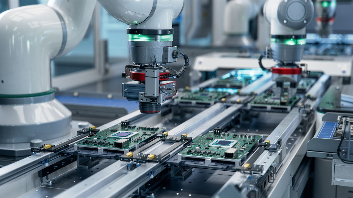
Modern human-machine interfaces (HMIs) are evolving rapidly across factory floors worldwide. Traditional resistive touchscreens allowed operators to register only a single touch point at a time. Today, multi-touch HMI panels enable intuitive multi-finger gestures and concurrent multi-operator inputs in demanding industrial automation setups.