


Product Details
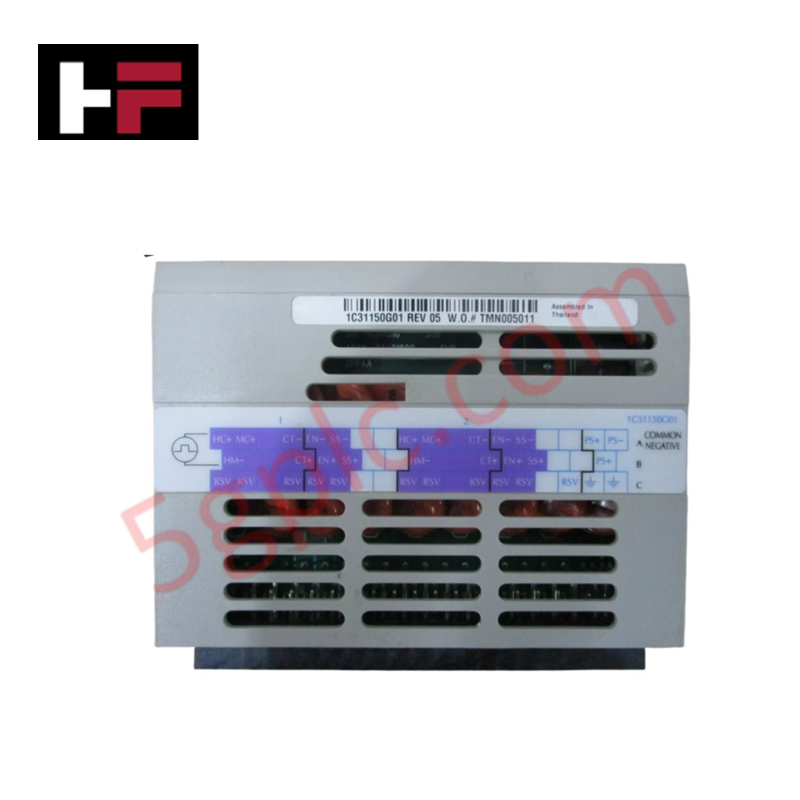
Configured for pulse frequency monitoring in WDPF control platforms, the Westinghouse 1C31150G01 (1C31150G01 Industrial Control Module) provides direct physical execution of signal accumulation and digital conversion for industrial process inputs.
Hardware Specifications
| Parameter | Specification |
|---|---|
| Model | 1C31150G01 |
| Brand | Westinghouse |
| Origin | Manufacturer-defined |
| Weight | Standard module weight |
| Dimensions | Chassis-dependent form factor |
| Operating Temp | -20 deg C to +70 deg C |
| Power Consumption | System-dependent load |
| Input Voltage | 24 VDC (±10%) |
| I/O Channels | 8-16 configurable channels |
Backplane Bus Communication Velocity
The 1C31150G01 module integrates with the host controller backplane to transmit accumulated pulse data at deterministic rates. This module is engineered to process high-frequency pulse inputs without packet collision, ensuring that the totalized count remains synchronous with the control loop scan time. Compatibility with proprietary serial interfaces allows for firmware-level data handshake between the pulse accumulator logic and the main CPU. Module configuration parameters, including debounce filtering and scaling factors, are set via the backplane bus to ensure consistent communication across all operational modes.
Frequently Asked Questions
Q: Does the 1C31150G01 module support hot-swap capabilities in the control rack?
A: Module replacement must be performed with the chassis slot power inhibited to avoid backplane transients. Ensure the I/O points are properly masked in the engineering workstation software before attempting physical removal of the module.
Q: How is the pulse input threshold voltage determined for this module?
A: The input threshold is fixed to comply with standard 24 VDC industrial logic levels (±10%). Ensure the field signal source impedance and voltage levels are matched to the module input characteristics to prevent double-counting or pulse signal attenuation.
Field Installation Guidelines
- Verify the module slot address settings match the engineering configuration before inserting the 1C31150G01 into the chassis.
- Align the module with the backplane connectors, applying even pressure to seat the unit until the retention mechanism is fully locked.
- Terminate signal wiring to the interface terminals using shielded conductors, ensuring the shield drain wire is connected to the cabinet ground bus.
- Route input signal cables through dedicated wireways, maintaining a minimum separation distance from AC power cabling to prevent electromagnetic induction.
- Confirm signal integrity post-installation by observing the activity LEDs on the faceplate and monitoring the pulse counts via the system diagnostic console.
Additional Information
- 100% Genuine Parts: All products are original and authentic, ensuring reliable industrial performance.
- 30-Day Refund Guarantee: Return any in-stock item within 30 days in original, unopened packaging for a full refund (excluding shipping and fees).
- 12-Month Warranty: Covers defects in materials or workmanship; excludes misuse, normal wear, or unauthorized modifications.
- Worldwide Shipping: We ship via USPS, UPS, FedEx, and DHL. Delivery times vary by country and may be subject to customs or import fees.
- Support & Contact: Technical and warranty assistance is available anytime. Contact us here: Contact.
- Purchase Guidance: Check product specifications and compatibility carefully before ordering to ensure proper application.


Tech & Buying Guide

Navigating Industrial Automation Failures: Types, Causes, and Mitigation Strategies
Modern manufacturing relies heavily on automated control systems to maximize throughput and maintain product quality. However, unplanned downtime in industrial automation can cost facility operators thousands of dollars per hour. Understanding how programmable logic controllers (PLCs), distributed control systems (DCS), and field instrumentation fail empowers engineering teams to implement robust preventive maintenance strategies.

Essential Motion Control Commands: A Practical Guide for Engineers
Automation engineers often rely on precise position and speed control to drive modern factory machinery. Modern industrial systems, such as Programmable Logic Controllers (PLCs) and Distributed Control Systems (DCS), depend heavily on standardized motion instructions. Mastering these commands ensures operational safety, protects mechanical components, and optimizes cycle times across production lines.

The Role of Intrinsic Safety Barriers in PLC and DCS Architectures
Implementing robust protection in hazardous industrial environments represents a fundamental safety requirement in factory automation. Process facilities often handle volatile gases, dusts, and chemical agents that pose significant combustion risks. Consequently, control system engineers must deploy energy-limiting interfaces to isolate safe-area control cabinets from hazardous-area field instrumentation. This article examines the function, selection, and electrical principles of intrinsic safety barriers within modern PLC and DCS networks.