


Product Details
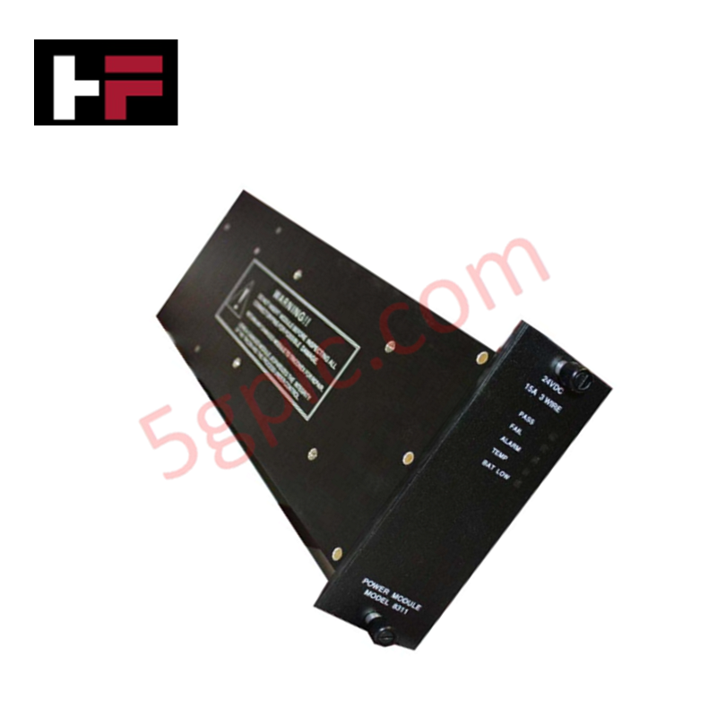
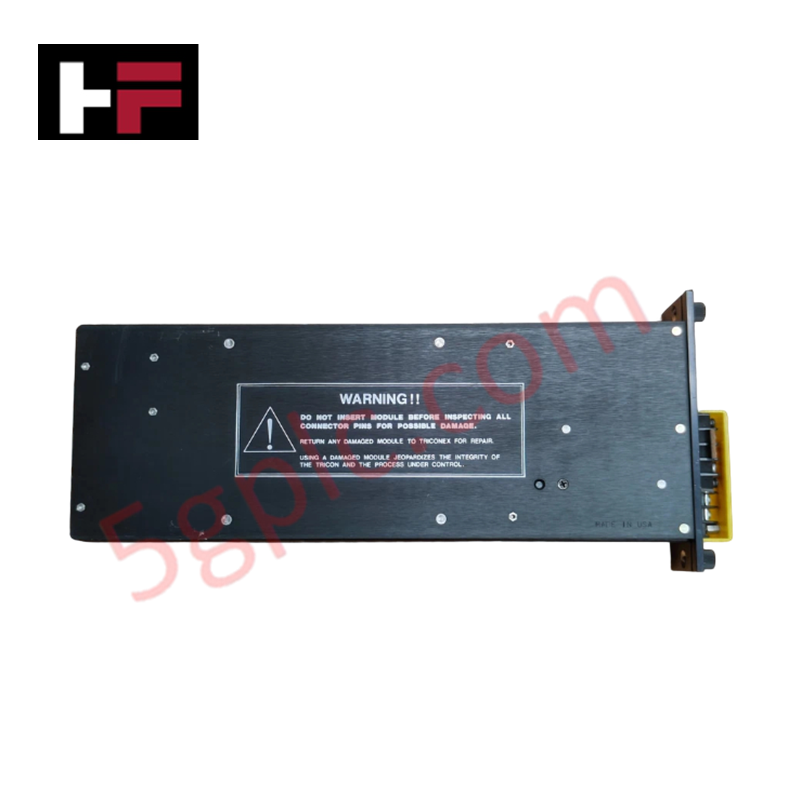
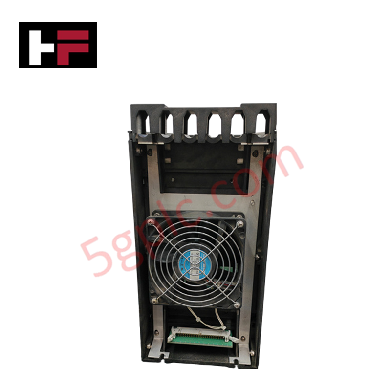
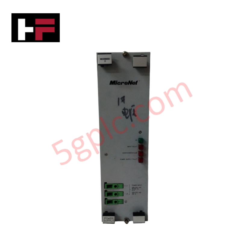
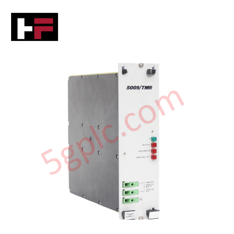
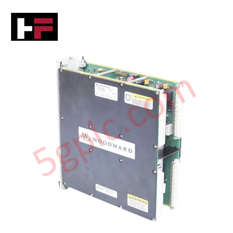
Configured for high-density DC power distribution in Tricon safety system platforms, the Triconex 8311 (8311 Power Supply High Density Module) provides direct physical/electrical execution of stable 24 VDC output regulation from a 22-31 VDC input range.
Hardware Specifications
| Parameter | Specification |
|---|---|
| Model | 8311 |
| Brand | Triconex |
| Weight | 2.7 kg |
| Dimensions | 43 mm x 27 mm x 32 mm |
| Operating Temp | Industrial standard range |
| Power Consumption | Not specified |
| Nominal Voltage | 24 VDC |
| Input VDC | 22-31 VDC |
| Fuse Rating | 15 A, time-delay |
| Output Hold Time | 2.8 ms minimum |
Triple Modular Redundancy (TMR) Architectural Integrity
The Triconex 8311 is designed to operate within a TMR 2oo3 architecture, providing high-availability power to Main, Expansion, and Remote Extender Module (RXM) chassis. To ensure continuous system uptime, the module incorporates galvanic isolation to decouple input DC transients from the system backplane power bus. In alignment with SIL3 certification requirements, the module supports fail-safe state execution; should an internal diagnostic monitoring circuit detect a power deviation or internal component failure, the module initiates a protective disconnect while signaling the failure status to the Tricon processors, allowing redundant power modules to sustain the load without impact to safety logic execution.
Frequently Asked Questions
Q: Does the 8311 module support hot-swapping during active system operation?
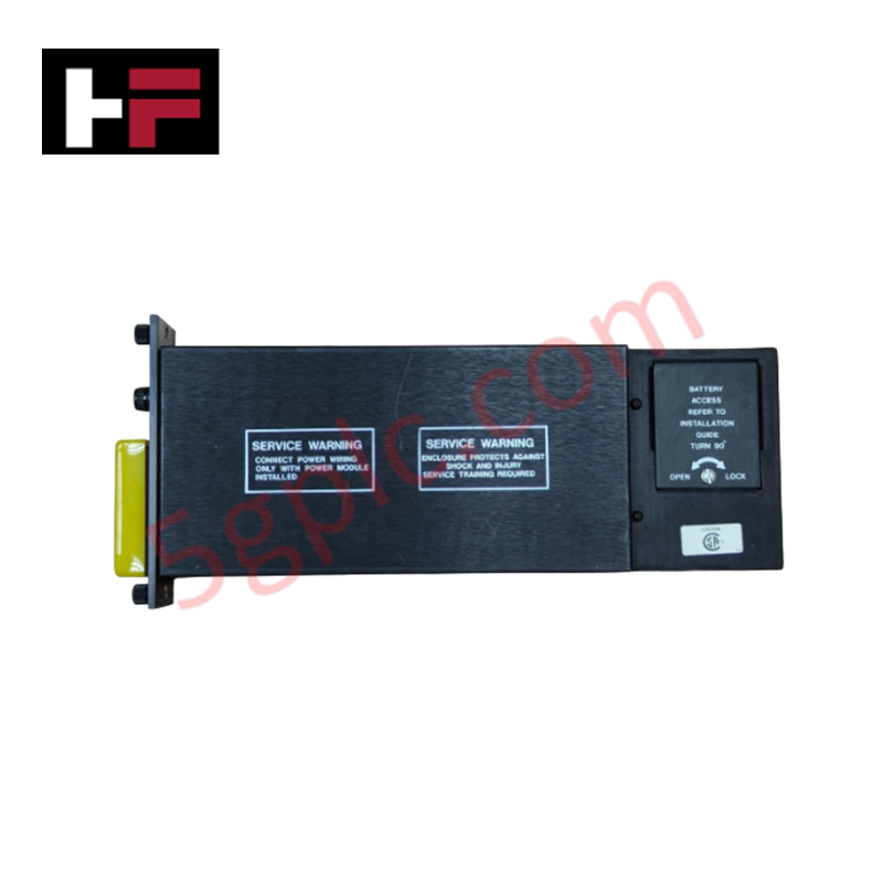
A: Yes, the 8311 is engineered for hot-swapping within the Tricon chassis. Before extraction, verify that the redundant power supply module is fully operational and capable of assuming the total system load to prevent power-bus interruptions.
Q: How does the output hold time affect system performance?
A: The 2.8 ms minimum output hold time provides the necessary buffer to maintain stable logic execution during momentary dips in the input voltage source, preventing unnecessary system resets or diagnostic errors.
Field Installation Guidelines
- Confirm the input DC source is within the 22-31 VDC range prior to connection to avoid activation of the internal 15 A fuse.
- Align the module with the chassis power slot and ensure full engagement with the backplane connectors to minimize contact resistance.
- Tighten the front-panel captive screws to establish the required electrical ground connection to the chassis frame.
- Ensure sufficient ventilation around the module to facilitate thermal dissipation, as the high-density power conversion generates heat during full-load operation.
- Use appropriately rated wiring for the DC input connections to prevent voltage drop and ensure that current carrying capacity matches the 15 A fuse rating.
Additional Information
- 100% Genuine Parts: All products are original and authentic, ensuring reliable industrial performance.
- 30-Day Refund Guarantee: Return any in-stock item within 30 days in original, unopened packaging for a full refund (excluding shipping and fees).
- 12-Month Warranty: Covers defects in materials or workmanship; excludes misuse, normal wear, or unauthorized modifications.
- Worldwide Shipping: We ship via USPS, UPS, FedEx, and DHL. Delivery times vary by country and may be subject to customs or import fees.
- Support & Contact: Technical and warranty assistance is available anytime. Contact us here: Contact.
- Purchase Guidance: Check product specifications and compatibility carefully before ordering to ensure proper application.
Tech & Buying Guide

Strategic Selection: Choosing the Right SCADA Software for Your PLC Project
In industrial automation, the SCADA (Supervisory Control and Data Acquisition) system acts as the bridge between raw machine data and actionable human intelligence. Selecting the incorrect software platform can lead to integration bottlenecks, scalability issues, and excessive long-term maintenance costs. As an automation consultant with 15 years of experience, I have guided many projects through the selection process. Below are the essential criteria for choosing a platform that ensures both performance and longevity.

Ensuring Operational Continuity: The Strategic Value of Redundant Automation Systems
In modern industrial landscapes, unplanned downtime is the ultimate adversary. For sectors relying on complex PLC and DCS architectures, a single hardware failure can trigger catastrophic production losses. Therefore, implementing redundant automation systems is no longer a luxury; it is a fundamental requirement for mission-critical operations. In this article, I analyze why redundancy remains the backbone of reliable industrial infrastructure.

Selecting the Right Cables for Industrial Automation: A Comprehensive Guide
Selecting the appropriate cabling infrastructure is critical for the success of any industrial automation project. Improper cable selection often leads to signal degradation, system instability, and costly downtime. As an automation engineer, I frequently see projects compromised by poor cabling choices in harsh industrial environments. This guide simplifies the complex landscape of cabling to help you make informed decisions for your PLC, DCS, and control systems.