


Product Details
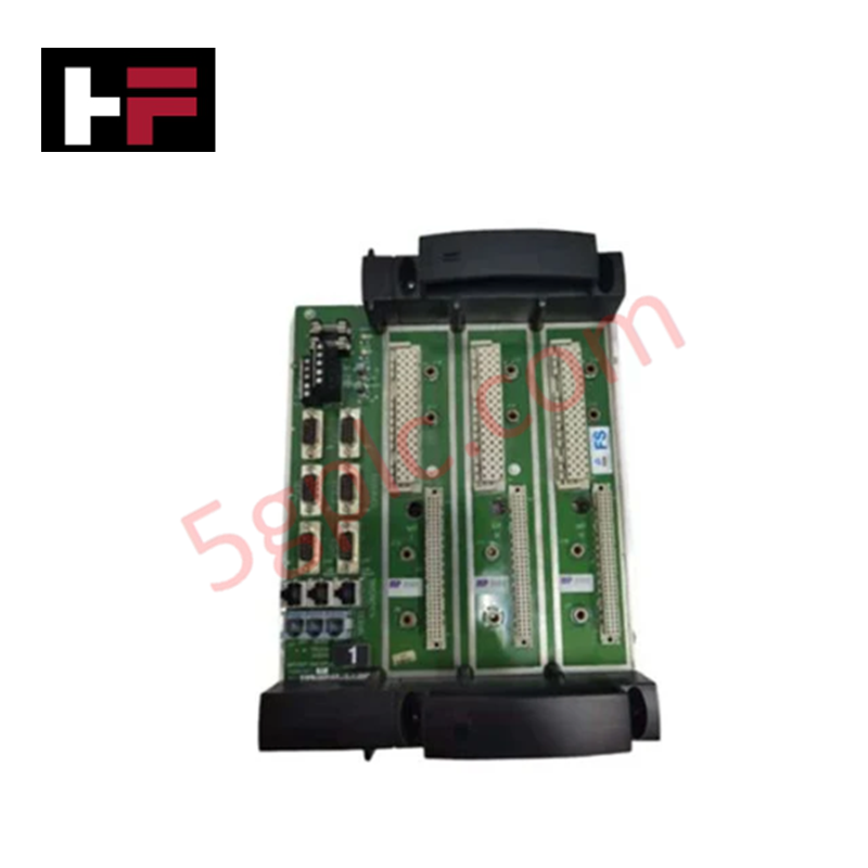
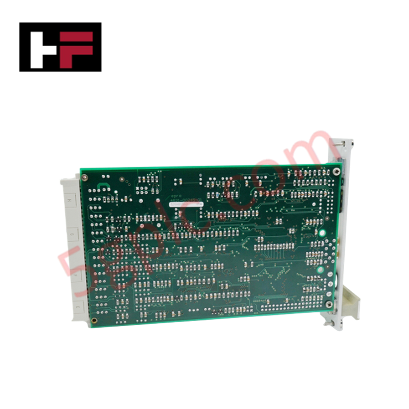
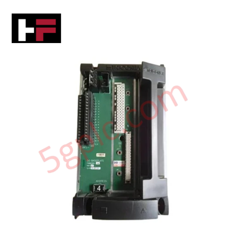
The Triconex 7400209-030 D02401, also cataloged as the 7400209-030 Digital Output Baseplate, operates as a dedicated hardware component for field wiring termination and signal distribution within Triconex safety-instrumented systems.
Hardware Specifications
| Parameter | Specification |
|---|---|
| Model | 7400209-030 D02401 |
| Brand | Triconex |
| Weight | 1.2 kg |
| Dimensions | 24.7 cm x 17.8 cm x 6.6 cm |
| Operating Temp | 0 deg C to 60 deg C |
| Power Consumption | Maximum 8 W |
| Capacity | 16 discrete digital output channels |
High-Reliability Safety Control and SIS Characteristics
The 7400209-030 baseplate serves as the physical interface for the D02401 digital output module, facilitating the routing of control signals to field-based actuators and logic devices. In the context of a triple modular redundancy (TMR) 2oo3 architecture, this baseplate ensures signal integrity and maintains path separation between redundant channels. It provides the necessary galvanic isolation between the field wiring interface and the internal system backplane to protect sensitive control circuitry from ground faults or surge events. The design supports the fail-safe state execution logic of the system by ensuring that all output paths are mechanically secured and electrically isolated according to safety-critical standards.
Frequently Asked Questions
Q: Does the baseplate require external power connection for channel operation?
A: Yes, the baseplate serves as the power distribution interface. Ensure the 24 VDC source is correctly wired to the power input terminals to support the 16 output channels and associated load current requirements.
Q: Are there specific grounding requirements for the baseplate assembly?
A: Yes. The baseplate must be bonded to the chassis ground to provide a common return path for shielding and to mitigate electromagnetic interference effects on the discrete output signals.
Field Installation Guidelines
- Secure the baseplate to the designated mounting surface within the Tricon chassis using standard fasteners.
- Verify that all field wiring for the 16 digital output channels is connected to the appropriate terminal blocks, ensuring proper orientation and polarity.
- Apply torque to terminal screws according to standard industrial practices to prevent high-resistance connections or intermittent signal loss.
- Route field cables in dedicated cable trays separate from high-voltage AC power lines to avoid induced noise on the output signals.
- Perform a continuity check between the field terminal points and the module insertion connectors to ensure path integrity before installing the digital output module.
Additional Information
- 100% Genuine Parts: All products are original and authentic, ensuring reliable industrial performance.
- 30-Day Refund Guarantee: Return any in-stock item within 30 days in original, unopened packaging for a full refund (excluding shipping and fees).
- 12-Month Warranty: Covers defects in materials or workmanship; excludes misuse, normal wear, or unauthorized modifications.
- Worldwide Shipping: We ship via USPS, UPS, FedEx, and DHL. Delivery times vary by country and may be subject to customs or import fees.
- Support & Contact: Technical and warranty assistance is available anytime. Contact us here: Contact.
- Purchase Guidance: Check product specifications and compatibility carefully before ordering to ensure proper application.


Tech & Buying Guide

Essential SCADA Features for Modern IoT-Enabled Industrial Automation
The convergence of traditional SCADA systems with the Industrial Internet of Things (IIoT) has redefined factory automation. Choosing a robust platform requires more than just standard monitoring capabilities. In this era of Industry 4.0, your supervisory system must bridge the gap between legacy control systems and enterprise-level data integration.

Selecting Rockwell Automation Allen-Bradley PLCs for Small and Mid-Sized Applications
Rockwell Automation remains a cornerstone in global industrial automation. Their Allen-Bradley brand provides a comprehensive portfolio of control systems designed to meet diverse production requirements. Choosing the right programmable logic controller (PLC) is critical for system reliability and scalability. This guide analyzes the Micro and Compact Logix families to help you select the optimal solution for small and medium-scale projects.

Strategic Selection: Choosing the Right SCADA Software for Your PLC Project
In industrial automation, the SCADA (Supervisory Control and Data Acquisition) system acts as the bridge between raw machine data and actionable human intelligence. Selecting the incorrect software platform can lead to integration bottlenecks, scalability issues, and excessive long-term maintenance costs. As an automation consultant with 15 years of experience, I have guided many projects through the selection process. Below are the essential criteria for choosing a platform that ensures both performance and longevity.