










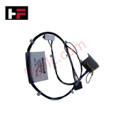
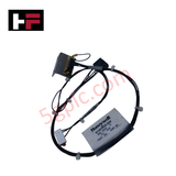
Product Details
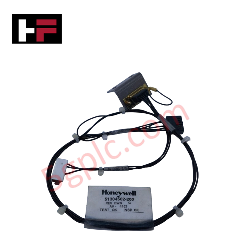
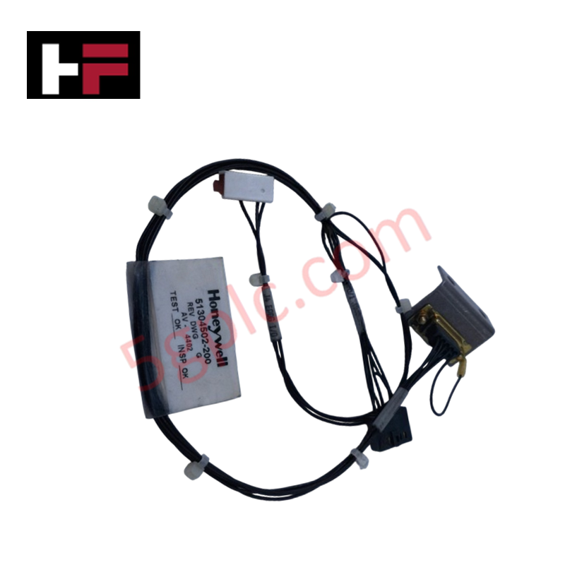
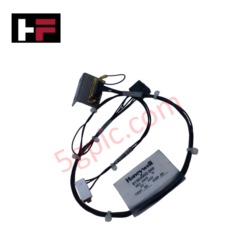
The Honeywell 51304502-200, also cataloged as the 51304502-200 Communication Cable Assembly, operates as a dedicated hardware component for high-integrity serial and network signal transmission within Honeywell Experion PKS and TDC 3000 systems. It links controller nodes, field I/O modules, and system infrastructure using shielded twisted-pair conductors to maintain signal propagation integrity under industrial electromagnetic conditions.
Hardware Specifications
| Parameter | Specification |
|---|---|
| Model | 51304502-200 |
| Brand | Honeywell |
| Origin | USA |
| Weight | 0.5 kg |
| Dimensions | 1-3 m standard length |
| Operating Temp | -20 to 60 deg C |
| Power Consumption | Passive component (0 W) |
| Cable Type | Communication Cable Assembly |
| Cable Construction | Shielded twisted-pair |
| Connector Type | Honeywell proprietary industrial connectors |
| Relative Humidity | 5% to 95% RH (non-condensing) |
| Compatible Systems | Honeywell Experion PKS, TDC 3000 |
Fieldbus Transmission & Channel-to-Channel Isolation Protection
High-density distributed control system architectures depend on clean signal pathways between controller backplanes and remote field I/O racks. The assembly utilizes continuous foil and braided shield layering to suppress capacitive and inductive cross-talk generated by high-voltage plant power lines. By preserving differential signal balances across the shielded twisted pairs, the cable supports stable communications alongside 4-20 mA HART loop protocol wiring and high-speed bus architectures without introducing frame drops or ground loop current interference.
Frequently Asked Questions
Q: What is the maximum recommended physical bend radius for this cable during installation?
A: To prevent conductor deformation, shield tearing, or impedance mismatches, maintain a minimum bend radius equal to at least 10 times the outer cable diameter during cabinet routing.
Q: How does the cable construction manage grounding to prevent ground loops?
A: Grounding is maintained through the continuous drain wire and connector shield shell, establishing a low-impedance ground path intended for single-point termination at the chassis enclosure ground bus.
Field Installation Guidelines
- Isolate and power down connected I/O racks or controller slots prior to attaching or disconnecting cable assemblies to avoid transient voltage spikes.
- Route the communication cable through dedicated low-voltage instrument wiring trays, keeping a minimum distance of 300 mm from high-voltage AC power conductors.
- Inspect the proprietary industrial connector pins for alignment, dirt, or mechanical damage before insertion.
- Fully seat the cable connectors into the module receptacles and hand-tighten any integral strain-relief screws to prevent accidental disconnects from operational vibration.
- Ensure the enclosure cable gland or clamp secures the outer jacket without crushing the internal shielded twisted pairs.
Additional Information
- 100% Genuine Parts: All products are original and authentic, ensuring reliable industrial performance.
- 30-Day Refund Guarantee: Return any in-stock item within 30 days in original, unopened packaging for a full refund (excluding shipping and fees).
- 12-Month Warranty: Covers defects in materials or workmanship; excludes misuse, normal wear, or unauthorized modifications.
- Worldwide Shipping: We ship via USPS, UPS, FedEx, and DHL. Delivery times vary by country and may be subject to customs or import fees.
- Support & Contact: Technical and warranty assistance is available anytime. Contact us here: Contact.
- Purchase Guidance: Check product specifications and compatibility carefully before ordering to ensure proper application.


Tech & Buying Guide

Understanding Marshalling Cabinets in Industrial Automation and Control Systems
Marshalling cabinets serve as the crucial connection hub between field instruments and centralized processing units. In large DCS and PLC control system architectures, hundreds of multipair field cables run from local junction boxes to the central instrument equipment room. The marshalling cabinet houses field terminal blocks, surge arresters, intrinsic safety isolation barriers, and interposing relays. By segregating field field-wiring terminations from sensitive processor hardware, engineers protect expensive controller backplanes from high-voltage transients. Consequently, this modular separation dramatically streamlines maintenance workflows and simplifies system expansion.

Essential Best Practices for PLC Wiring and Installation in Industrial Automation
Successful control system deployment begins with thoroughly reviewing manufacturer technical documentation. Controllers from major brands like Allen-Bradley, Siemens, and Schneider Electric feature unique terminal layouts. Engineers must verify voltage requirements before connecting power cables to prevent catastrophic equipment damage. Standard line connections require strict adherence to regional electrical codes and proper wire color coding. Furthermore, panel builders should always establish a robust low-impedance ground connection using at least 16-AWG copper conductor tied directly to the main plant grounding grid.

Demystifying Programmable Logic Controllers: Comprehensive Guide to PLC Classification and Selection in Industrial Automation
Modern industrial automation heavily relies on Programmable Logic Controllers (PLCs) to drive factory floor efficiency. Over my 15 years as an industrial automation expert working with DCS, TSI, and control systems, I have seen PLCs evolve into the central nervous system of modern manufacturing. Selecting the right controller requires a deep understanding of PLC types based on physical size, hardware architecture, and power supply configurations.