


Product Details
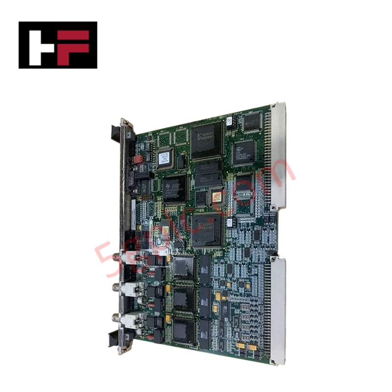
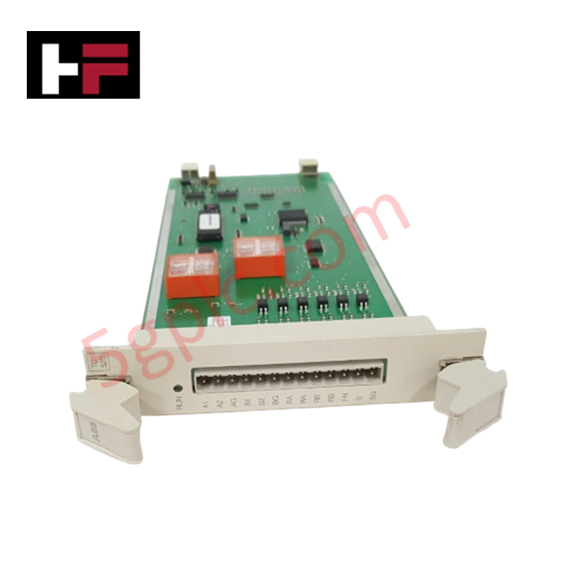
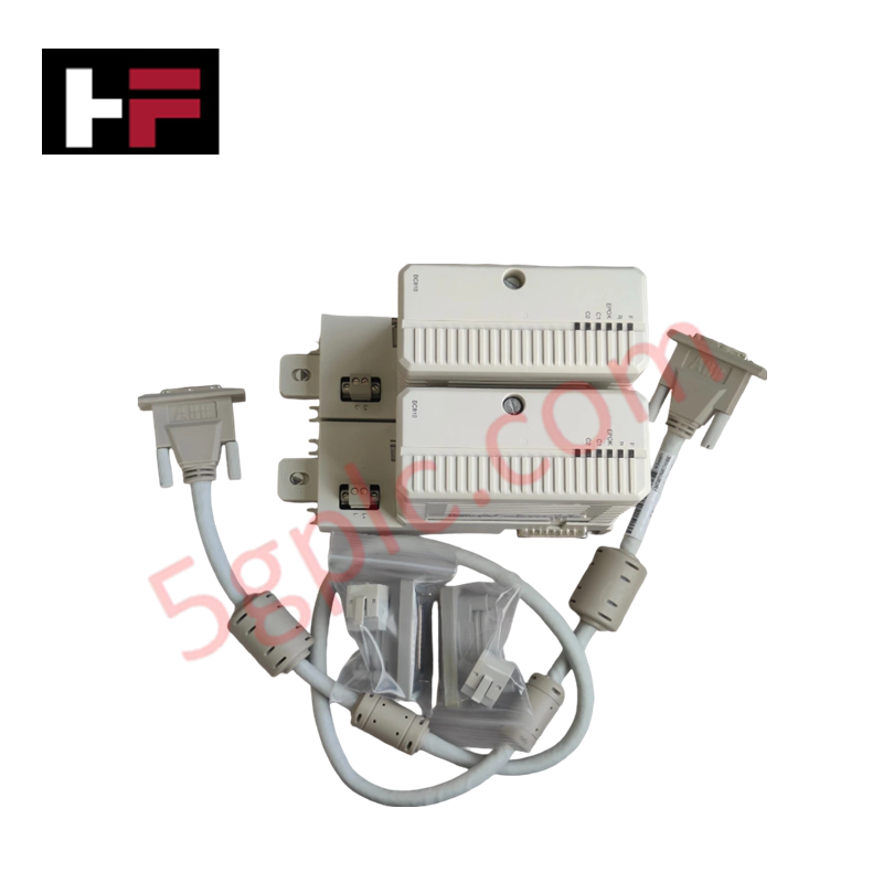
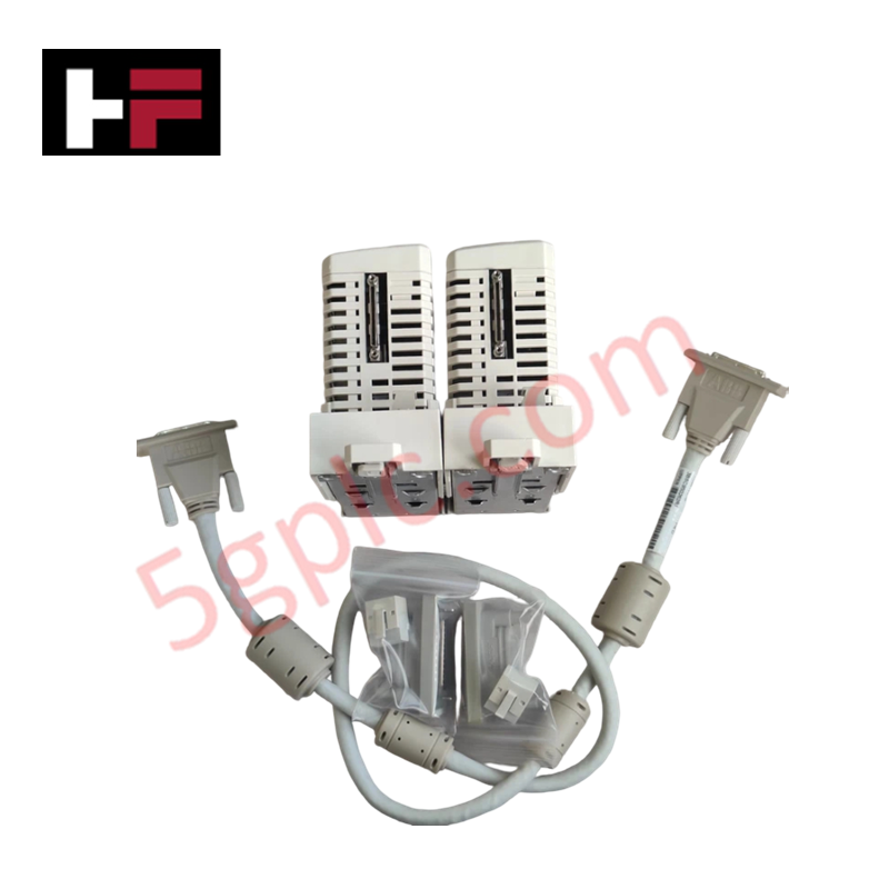
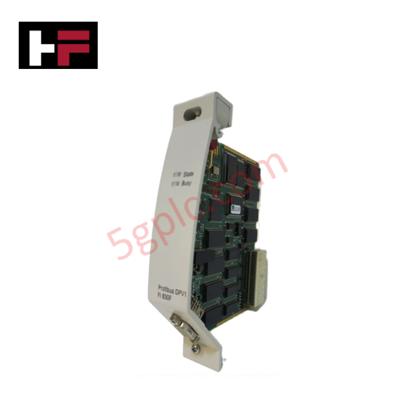
Configured for internal network management in Mark VI Speedtronic control platforms, the GE IS200VCMIH2B (IS200VCMIH2B VME Communications Interface) provides direct physical execution of backplane data exchange. This hardware component serves as the primary VME bus master controller utilized to execute inter-module communication across Control and Protection Modules within the Mark VI rack architecture.
Hardware Specifications
| Parameter | Specification |
|---|---|
| Model | IS200VCMIH2B |
| Brand | GE |
| Dimensions | Standard VME board form factor |
| Operating Temp | Standard indoor air-cooled range |
| Power Consumption | 125 V dc |
| Core Performance | VME bus master; 3 IONet ports; 9-pin serial interface |
Industrial Control and Firmware Compatibility
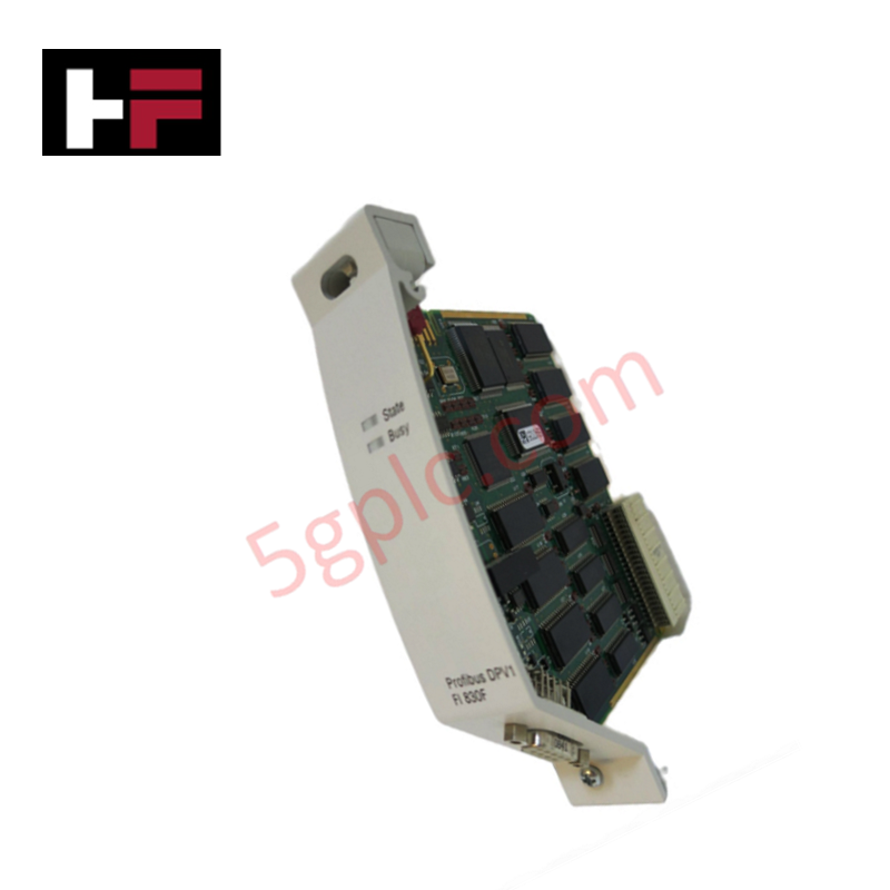
The IS200VCMIH2B is installed in slot one of the Central Control Module, facilitating high-speed data transfer between I/O cards, control modules, and protection modules. The module supports I/O density scaling by coordinating multiple network segments through three dedicated DIN connectors (IONet1 through IONet3). Deterministic backplane bus communication velocity is maintained through two onboard field-programmable gate arrays (FPGAs), which manage signal routing and data packet prioritization. Firmware flash compatibility is strictly enforced through the ControlST software suite, requiring exact version matching between the VCMI processor and the host controller to ensure synchronized operation. The board’s architecture includes extensive onboard diagnostics via front-faceplate LED arrays, providing real-time status visibility for network activity and board health.
Frequently Asked Questions
Q: Is the IS200VCMIH2B hot-swappable in the Mark VI rack?
A: No. The VME backplane connection does not support live insertion or removal. The chassis power must be isolated and the board de-energized before extraction to prevent electrical damage to the backplane connectors and the high-density surface-mount components.
Q: What is the purpose of the 9-pin serial connector on the faceplate?
A: The 9-pin male serial connector serves as a local engineering interface for diagnostic polling and system configuration. It is not intended for high-speed continuous control data bus communication.
Field Installation Guidelines
- Mounting: Ensure the board is aligned with the slot one guide rails of the Central Control Module. Seat the board firmly to ensure full engagement of the backplane connectors.
- Grounding: The PCB must maintain a secure electrical path to the rack chassis ground. Ensure the faceplate mounting screws are tightened to the specified torque to maintain electromagnetic compatibility (EMC) shielding.
- Cabling: Utilize shielded cables for all IONet connections to prevent crosstalk. Ensure cables are strain-relieved to prevent mechanical stress on the faceplate DIN connectors.
- Verification: Perform a power-up diagnostic check via the system engineering software to confirm that all three IONet ports and the VME bus interface are correctly initialized before placing the control module into service.
Additional Information
- 100% Genuine Parts: All products are original and authentic, ensuring reliable industrial performance.
- 30-Day Refund Guarantee: Return any in-stock item within 30 days in original, unopened packaging for a full refund (excluding shipping and fees).
- 12-Month Warranty: Covers defects in materials or workmanship; excludes misuse, normal wear, or unauthorized modifications.
- Worldwide Shipping: We ship via USPS, UPS, FedEx, and DHL. Delivery times vary by country and may be subject to customs or import fees.
- Support & Contact: Technical and warranty assistance is available anytime. Contact us here: Contact.
- Purchase Guidance: Check product specifications and compatibility carefully before ordering to ensure proper application.
Tech & Buying Guide

Mastering the Factory Acceptance Test (FAT) for PLC Control Panels: An Expert Guide
The Factory Acceptance Test (FAT) is a vital milestone in industrial automation that ensures custom PLC panels meet exact design specifications before dispatch. This guide outlines the step-by-step FAT procedure and key industry best practices to prevent costly site delays and ensure long-term operational success.

Redundant Automation Systems: Ensuring Continuous Uptime in Critical Control Infrastructure
System reliability directly determines operational profitability across high stakes process industries. Modern industrial automation platforms must eliminate single points of failure to prevent catastrophic shutdowns. Deploying fault tolerant architecture safeguards complex facilities against unexpected hardware glitches, network disruptions, and maintenance outages.

Understanding Types of Noise in Electronic Circuits and Control Systems
Signal integrity directly determines measurement accuracy and loop stability across industrial automation environments. Electronic noise introduces unwanted stochastic interference into analog loops, sensor feedback lines, and digital fieldbus networks. Understanding how intrinsic electronic noise and external electromagnetic interference manifest allows control engineers to optimize signal conditioning and shield sensitive instrumentation effectively.