


Product Details
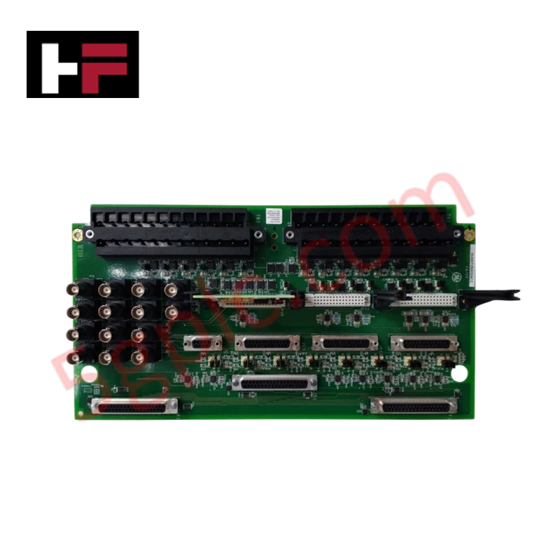
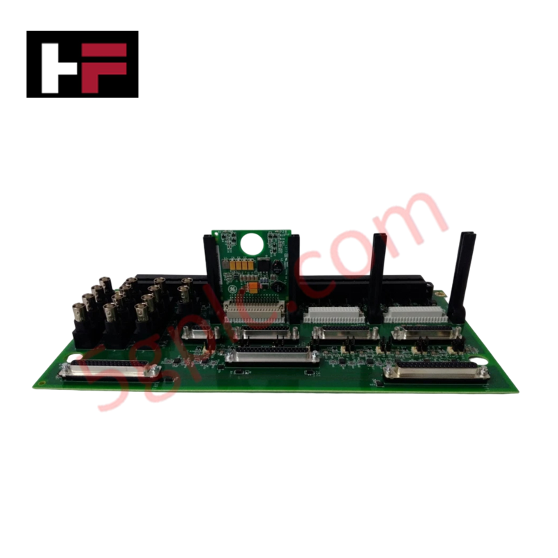
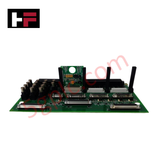
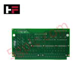
Configured for seismic and proximity sensor signal conditioning in Mark VIe turbine monitoring systems, the GE FANUC IS200TVBAH2ACC (IS200TVBAH2ACC Vibration Input Terminal Board) provides direct physical and electrical execution of vibration signal routing and sensor excitation.
Hardware Specifications
| Parameter | Specification |
|---|---|
| Model | IS200TVBAH2ACC |
| Brand | GE Fanuc |
| Origin | USA |
| Weight | 0.99 kg |
| Dimensions | 34.1 cm x 21.6 cm x 5.5 cm |
| Operating Temp | -40 deg C to 70 deg C |
| Power Consumption | 10-30 VDC |
| Input Channels | 13 (8 vibration, 4 vibration/position, 1 Keyphasor) |
| Output | Buffered BNC, DB9, DB25 |
Gap Voltage Validation and Mechanical Monitoring
The IS200TVBAH2ACC functions as the primary interface for rotor dynamics analysis, processing raw inputs from seismic sensors, Velomitors, and accelerometers. The module performs essential gap voltage validation, maintaining -24 VDC excitation per channel to power proximity probes, with current output capabilities up to 12 mA. Eddy-current probe scaling is processed to ensure that static and dynamic displacement signals are accurately relayed to the monitoring system. Cross-talk suppression is maintained through internal circuit isolation, ensuring signal integrity for the Keyphasor reference probe and associated vibration circuits. Buffered outputs via BNC and D-sub connectors allow for external diagnostic equipment connectivity without loading the primary monitoring signal path.
Frequently Asked Questions
Q: Can the IS200TVBAH2ACC be hot-swapped while the turbine monitoring system is operational?
A: No. The board must be de-energized to prevent electrical transients from disrupting the monitoring signal path or potentially causing damage to the backplane communication circuitry.
Q: How is the Keyphasor signal reference maintained during system operation?
A: The Keyphasor signal is processed through the dedicated 13th channel circuit, providing the timing reference for rotor dynamics and phase analysis. Ensure probe installation meets the specific angular and gap requirements for the monitored shaft.
Field Installation Guidelines
- Mounting: Secure the board using the designated chassis mounting points. Ensure the assembly is properly grounded to the cabinet chassis to minimize common-mode noise on the vibration signals.
- Wiring: Use shielded, twisted-pair cabling for all proximity and seismic sensor inputs. Bond cable shields at the terminal board grounding bus to prevent electromagnetic interference (EMI) from affecting the low-level vibration data.
- Connectivity: Utilize the factory-provided BNC, DB9, or DB25 connectors for buffered signal output. Ensure these connectors are fully seated and free from moisture or contamination, which can cause signal drift.
- Environment: Operate the module within the specified -40 deg C to 70 deg C range. In harsh industrial environments, confirm the cabinet maintains internal conditions consistent with the board's environmental rating.
- Verification: Following installation, perform a gap voltage check for all proximity probe channels. Verify that the output voltage corresponds to the expected probe calibration curve within the monitoring software.
Additional Information
- 100% Genuine Parts: All products are original and authentic, ensuring reliable industrial performance.
- 30-Day Refund Guarantee: Return any in-stock item within 30 days in original, unopened packaging for a full refund (excluding shipping and fees).
- 12-Month Warranty: Covers defects in materials or workmanship; excludes misuse, normal wear, or unauthorized modifications.
- Worldwide Shipping: We ship via USPS, UPS, FedEx, and DHL. Delivery times vary by country and may be subject to customs or import fees.
- Support & Contact: Technical and warranty assistance is available anytime. Contact us here: Contact.
- Purchase Guidance: Check product specifications and compatibility carefully before ordering to ensure proper application.


Tech & Buying Guide

Navigating Industrial Automation Failures: Types, Causes, and Mitigation Strategies
Modern manufacturing relies heavily on automated control systems to maximize throughput and maintain product quality. However, unplanned downtime in industrial automation can cost facility operators thousands of dollars per hour. Understanding how programmable logic controllers (PLCs), distributed control systems (DCS), and field instrumentation fail empowers engineering teams to implement robust preventive maintenance strategies.

Essential Motion Control Commands: A Practical Guide for Engineers
Automation engineers often rely on precise position and speed control to drive modern factory machinery. Modern industrial systems, such as Programmable Logic Controllers (PLCs) and Distributed Control Systems (DCS), depend heavily on standardized motion instructions. Mastering these commands ensures operational safety, protects mechanical components, and optimizes cycle times across production lines.

The Role of Intrinsic Safety Barriers in PLC and DCS Architectures
Implementing robust protection in hazardous industrial environments represents a fundamental safety requirement in factory automation. Process facilities often handle volatile gases, dusts, and chemical agents that pose significant combustion risks. Consequently, control system engineers must deploy energy-limiting interfaces to isolate safe-area control cabinets from hazardous-area field instrumentation. This article examines the function, selection, and electrical principles of intrinsic safety barriers within modern PLC and DCS networks.