

Product Details
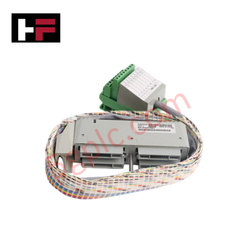
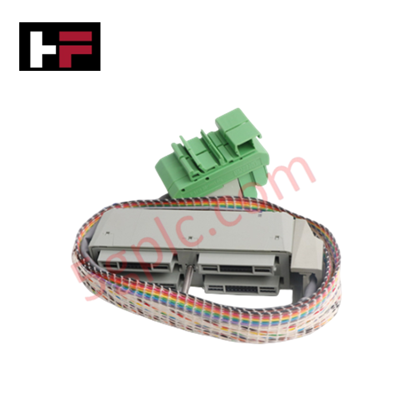
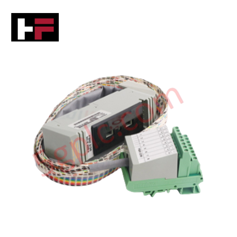
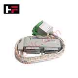
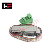
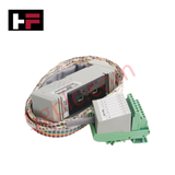
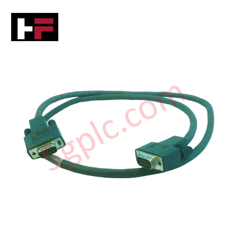
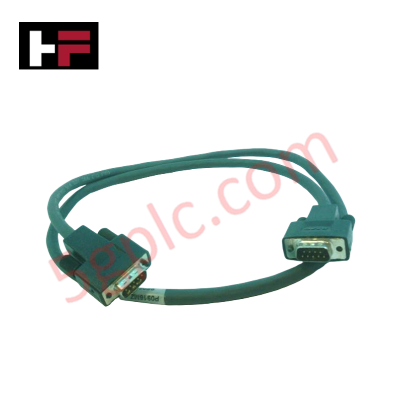
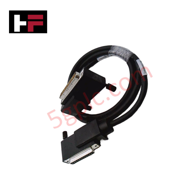
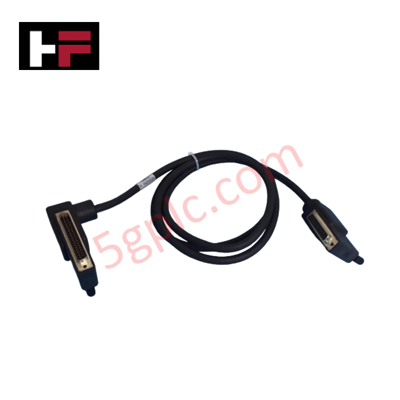
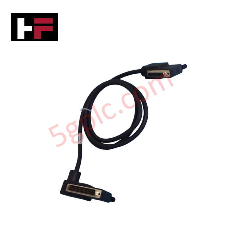
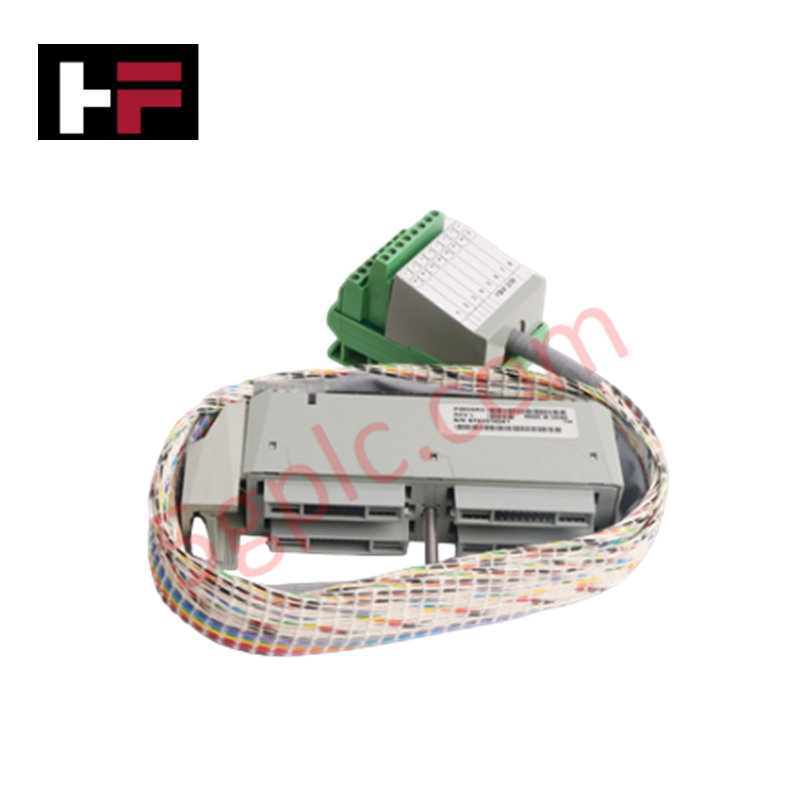
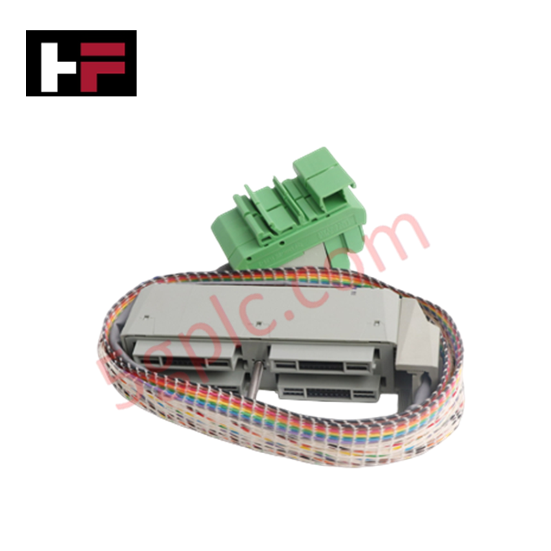
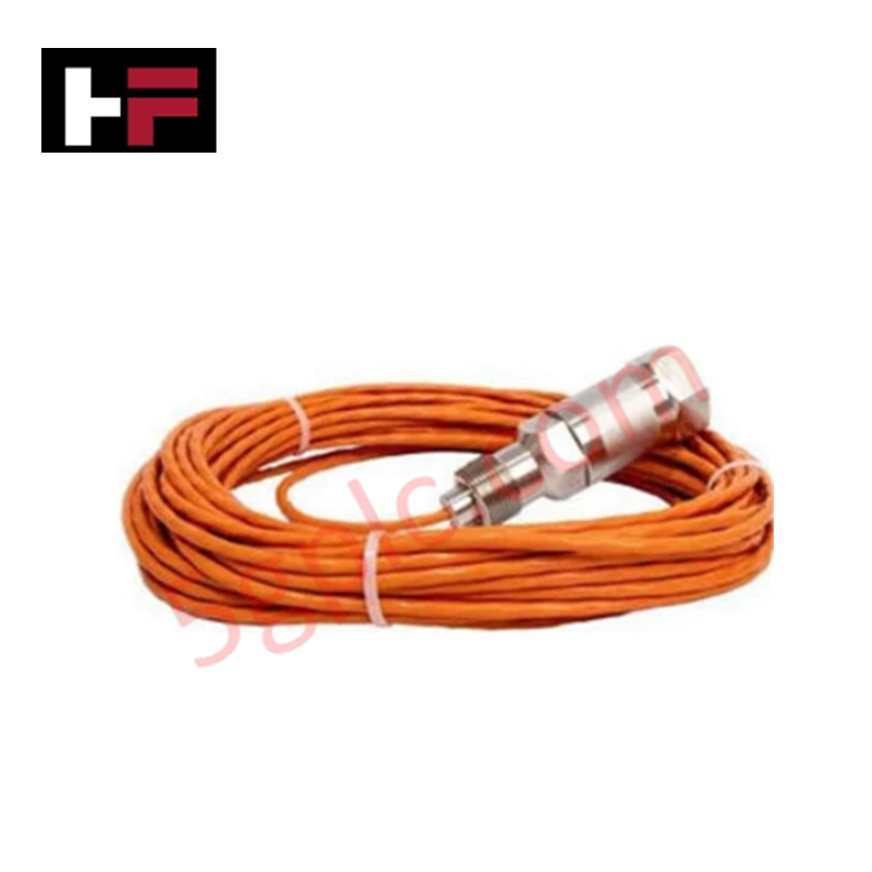
The Foxboro P0500RY, also cataloged as the P0500RY Termination Cable, serves as the primary P0500RY Termination Cable utilized to execute field signal interconnection between FBM4, FBM39, and FBM44 Fieldbus Modules across I/A Series platforms. It provides point-to-point electrical connectivity for analog and discrete signal conditioning.
Hardware Specifications
| Parameter | Specification |
|---|---|
| Model | P0500RY |
| Brand | Foxboro |
| Origin | USA |
| Weight | 0.36 kg |
| Dimensions | 140 cm x 15.5 cm x 4.5 cm |
| Module Compatibility | FBM4, FBM39, FBM44 |
| Operating Temp | -20 to +70 deg C |
| Power Consumption | Passive (0 W) |
| Cable Type | Prefabricated I/A Series Termination Cable |
Channel-to-Channel Isolation & Signal Integrity
The Foxboro P0500RY termination cable maintains signal integrity within I/A Series system architectures by providing high-noise-immunity signal pathways for 4-20 mA HART loop protocol interconnections and discrete input/output field wiring assemblies. Constructed with high-density shielding to minimize magnetic coupling and signal crosstalk, the assembly preserves channel-to-channel isolation parameters established across the parent Fieldbus Modules (FBM4, FBM39, FBM44) and baseplate assemblies. The molded connector housing incorporates grounding strain relief to ensure signal stability in high-vibration industrial cabinet environments.
Frequently Asked Questions
Q: Can the Foxboro P0500RY cable be connected or disconnected while the system is powered?
A: Fieldbus module baseplates support hot-swapping, but field signal wiring associated with the P0500RY cable should be isolated or power-limited prior to disconnection to prevent unexpected trip signals or transient arcs in field devices.
Q: Does the P0500RY cable contribute to the total power budget of the I/A Series baseplate?
A: No, the P0500RY is a passive copper cable assembly that introduces negligible resistance and does not draw power from the backplane bus.
Field Installation Guidelines
- Inspect cable connectors and pinning prior to insertion to ensure pins are straight and clean.
- Maintain a minimum bend radius of 75 mm along the cable run to prevent conductor stress and insulation degradation.
- Route the termination cable through dedicated instrument wire ducts, separated from high-voltage power cables by at least 300 mm.
- Ensure full mating engagement of the connector assembly with the FBM baseplate header, securing retention screws hand-tight.
- Connect cable shield drains directly to the cabinet signal ground bus bar following single-point grounding rules to prevent ground loops.
Additional Information
- 100% Genuine Parts: All products are original and authentic, ensuring reliable industrial performance.
- 30-Day Refund Guarantee: Return any in-stock item within 30 days in original, unopened packaging for a full refund (excluding shipping and fees).
- 12-Month Warranty: Covers defects in materials or workmanship; excludes misuse, normal wear, or unauthorized modifications.
- Worldwide Shipping: We ship via USPS, UPS, FedEx, and DHL. Delivery times vary by country and may be subject to customs or import fees.
- Support & Contact: Technical and warranty assistance is available anytime. Contact us here: Contact.
- Purchase Guidance: Check product specifications and compatibility carefully before ordering to ensure proper application.

Tech & Buying Guide

Managed Switch vs. Unmanaged Switch: Industrial Ethernet Architecture

Hot Standby vs. Cold Standby Redundancy in Industrial Automation
System availability determines process safety and productivity in industrial automation. Control engineers deploy redundancy to eliminate single points of failure. This technical guide evaluates Hot Standby vs. Cold Standby architectures, comparing failover speeds, memory sync, cost trade-offs, and field selection criteria.