

Product Details
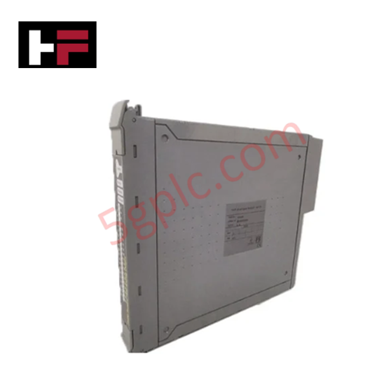
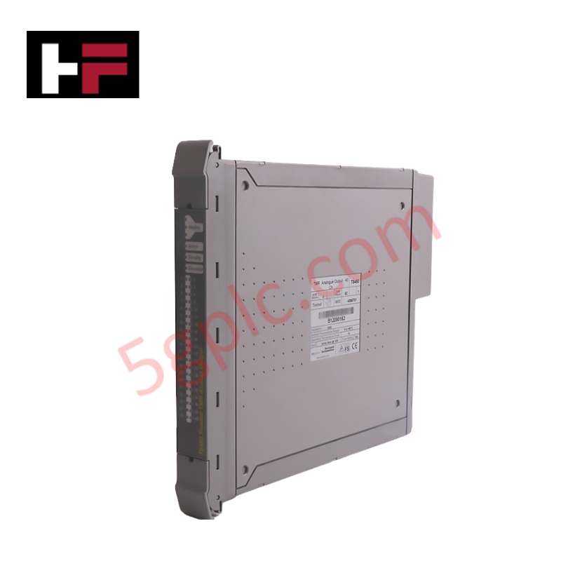
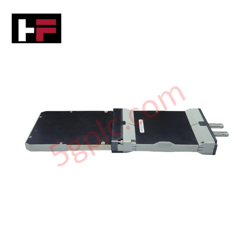
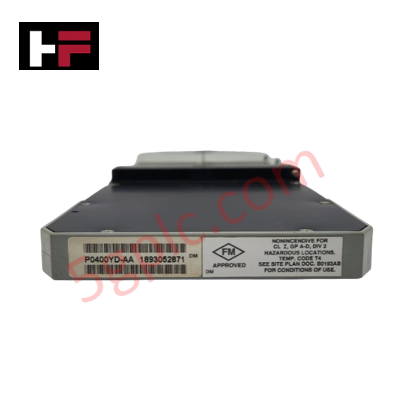
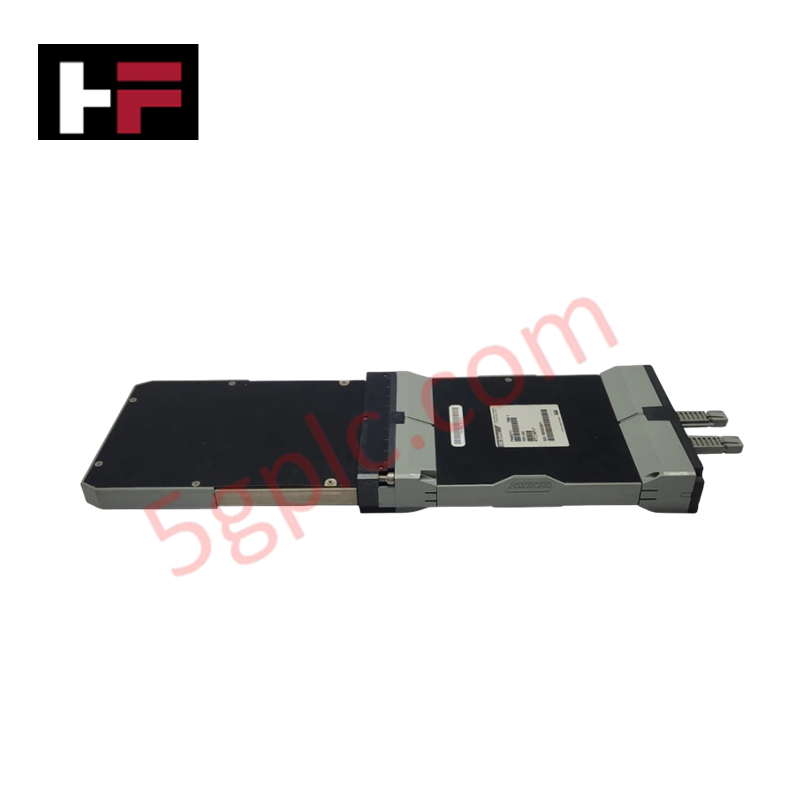
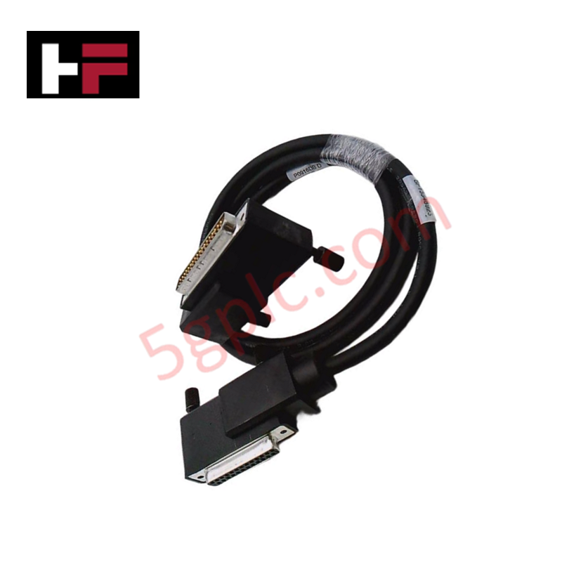
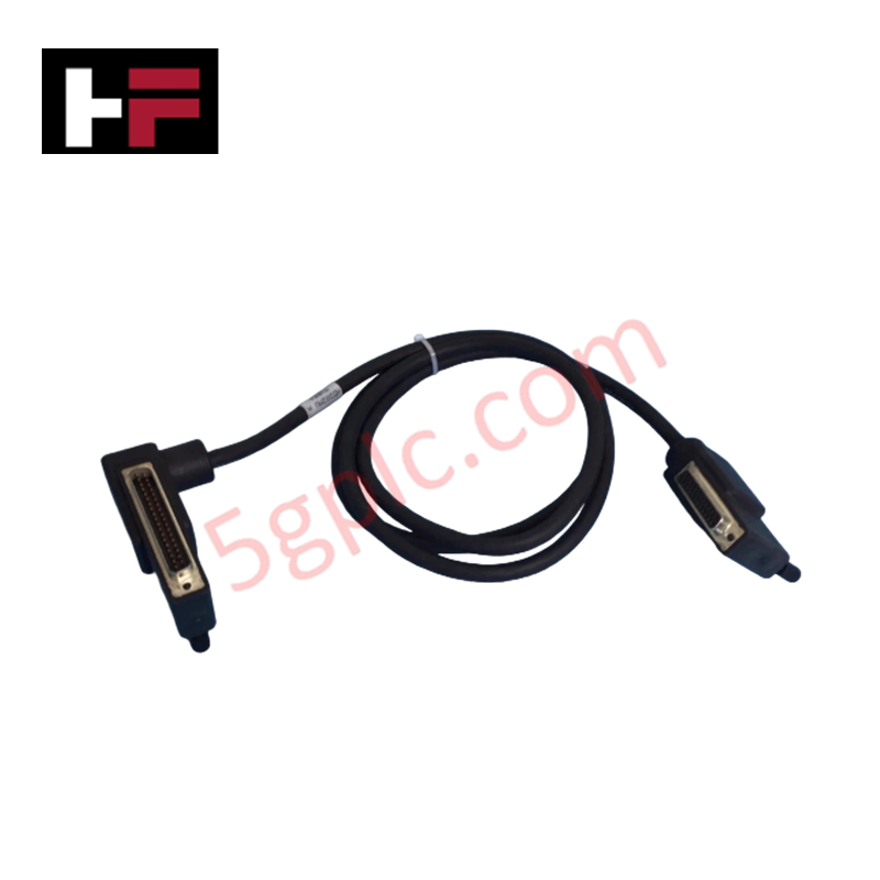
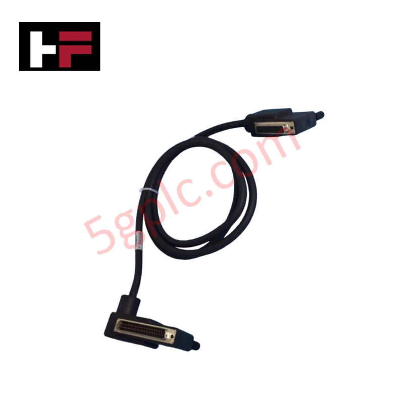
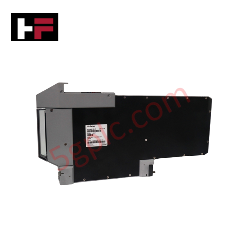
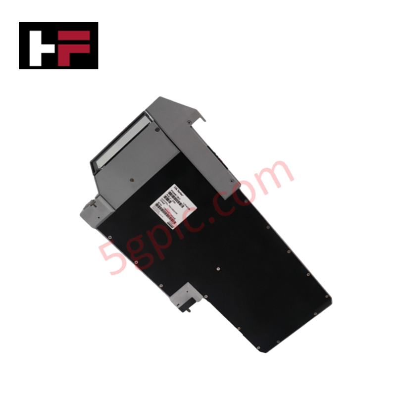
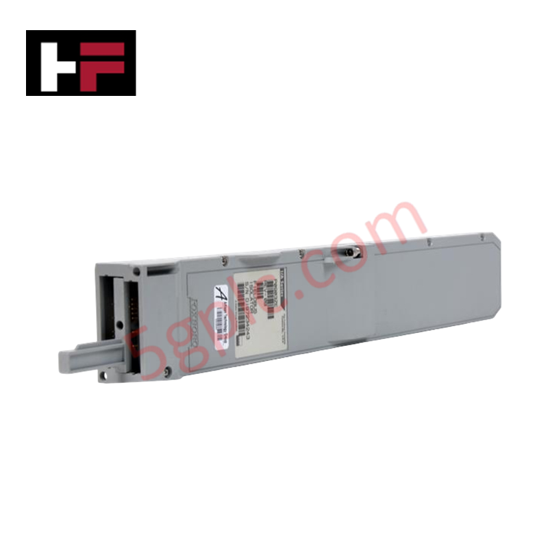
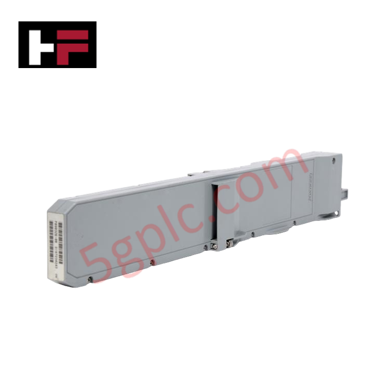
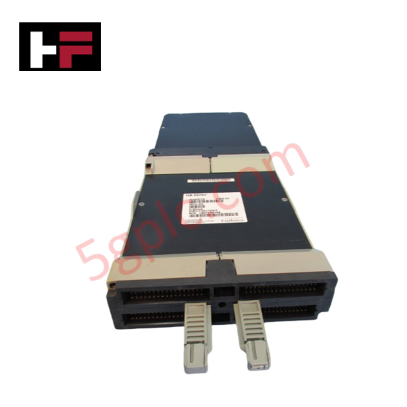
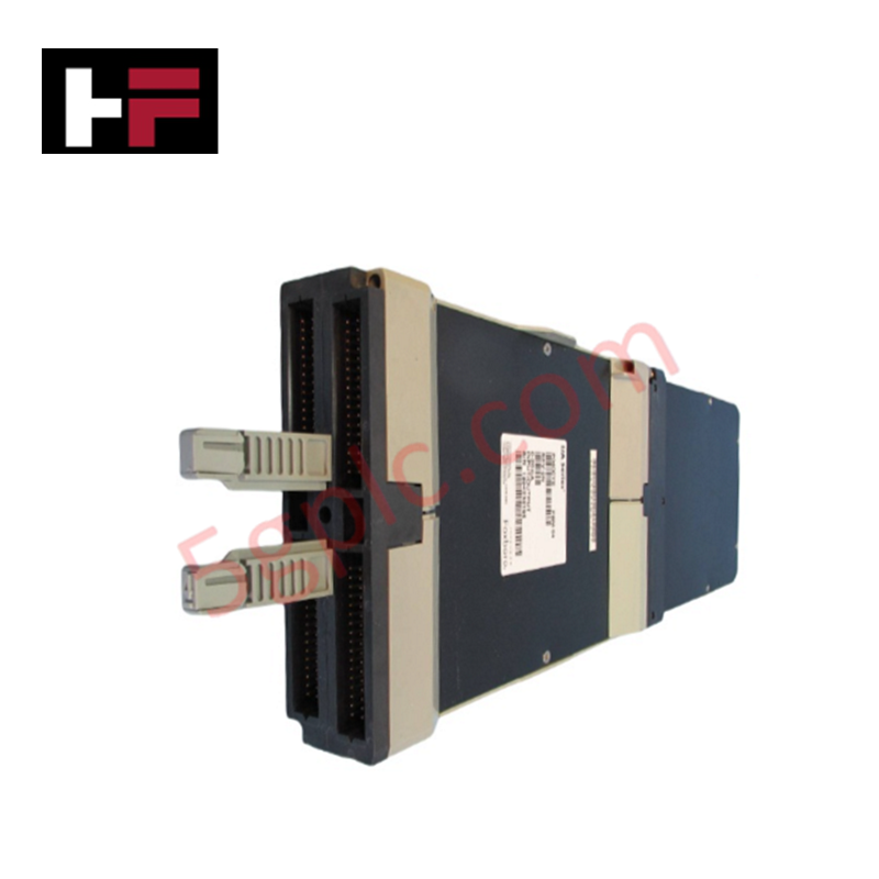
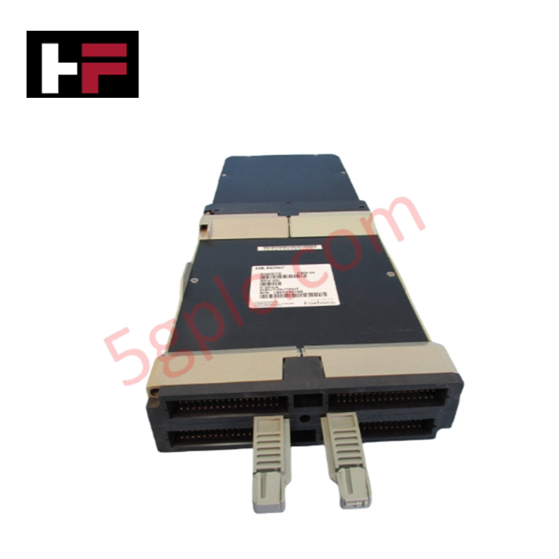
Configured for resistance temperature detector signal conditioning and analog input conversion in Foxboro I/A Series DCS networks, the Foxboro P0400YD FBM3 (P0400YD RTD Input Module) provides direct physical/electrical execution. Operating on a 24 VDC nominal supply (+/-10%), the module acquires temperature signals across 16 channels, transmitting digitized process values over the Foxboro FBM bus protocol.
Hardware Specifications
| Parameter | Specification |
|---|---|
| Model | P0400YD FBM3 |
| Brand | Foxboro |
| Origin | USA |
| Operating Temp | -40 deg C to +70 deg C |
| Power Consumption | 24 VDC (+/-10%) supply voltage |
| Input Channels | 16 channels |
| Signal Accuracy | +/-0.1% of full scale |
| Electrical Isolation | 1500 VAC channel-to-channel isolation |
| System Compatibility | Foxboro I/A Series FBM Subsystems |
Channel-to-Channel Isolation and Loop Protocol Connectivity
The Foxboro P0400YD FBM3 module incorporates 1500 VAC galvanic channel-to-channel isolation barriers to eliminate common-mode ground loop currents and field voltage spikes. Integrated thermal compensation logic protects RTD bridge measurement circuits from noise interference, maintaining linear analog conversion accuracy and preventing cold junction compensation (CJC) signal skew across 4-20 mA HART loop protocol interfaces.
Frequently Asked Questions
Q: Does the P0400YD FBM3 module support live replacement during active system operation?
A: Yes, the module supports hot-swapping on energized baseplates, enabling online hardware replacement without interrupting bus communications on adjacent slots.
Q: What isolation level is maintained between individual input channels on the P0400YD FBM3?
A: The hardware provides 1500 VAC channel-to-channel electrical isolation to protect system electronics against common-mode noise and ground potential differentials.
Field Installation Guidelines
Align the P0400YD FBM3 module with the guide channels on the target I/A Series baseplate slot and push firmly until the locking tabs secure the chassis connection. Verify that the 24 VDC field power supply stays within the +/-10% voltage tolerance limit prior to energizing the subsystem.
Route RTD and analog signal wiring using individual shielded twisted-pair cables, keeping sensor runs separated from high-voltage AC power conductors. Terminate cable drain shields directly at the cabinet earth bus bar, ensuring all panel conduit entry fittings maintain a minimum of 5 full threads of engagement on NPT connection points.
Additional Information
- 100% Genuine Parts: All products are original and authentic, ensuring reliable industrial performance.
- 30-Day Refund Guarantee: Return any in-stock item within 30 days in original, unopened packaging for a full refund (excluding shipping and fees).
- 12-Month Warranty: Covers defects in materials or workmanship; excludes misuse, normal wear, or unauthorized modifications.
- Worldwide Shipping: We ship via USPS, UPS, FedEx, and DHL. Delivery times vary by country and may be subject to customs or import fees.
- Support & Contact: Technical and warranty assistance is available anytime. Contact us here: Contact.
- Purchase Guidance: Check product specifications and compatibility carefully before ordering to ensure proper application.

Tech & Buying Guide

Managed Switch vs. Unmanaged Switch: Industrial Ethernet Architecture

Hot Standby vs. Cold Standby Redundancy in Industrial Automation
System availability determines process safety and productivity in industrial automation. Control engineers deploy redundancy to eliminate single points of failure. This technical guide evaluates Hot Standby vs. Cold Standby architectures, comparing failover speeds, memory sync, cost trade-offs, and field selection criteria.