

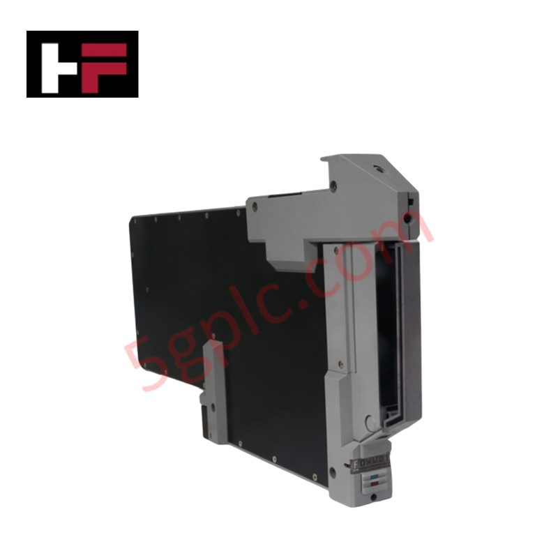
Product Details
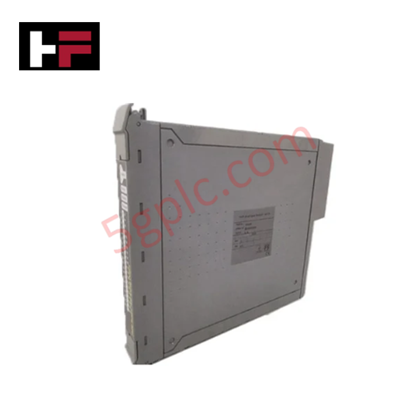
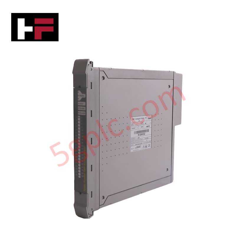
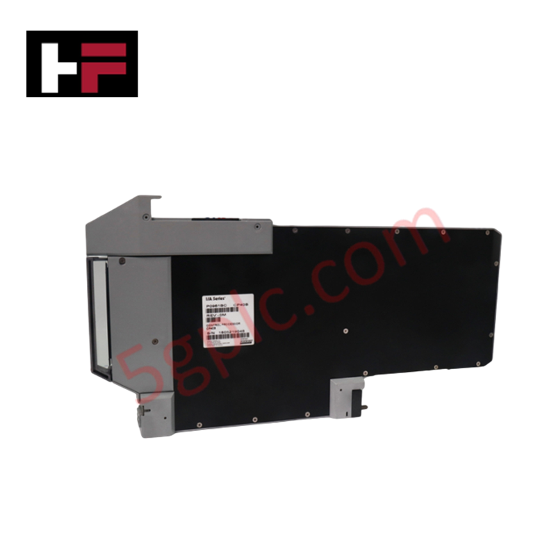
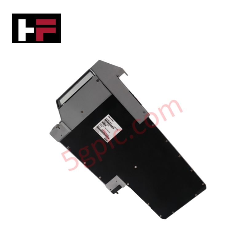
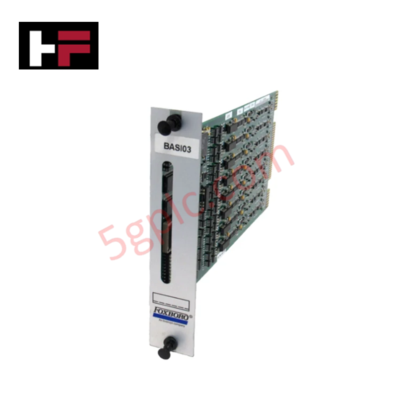
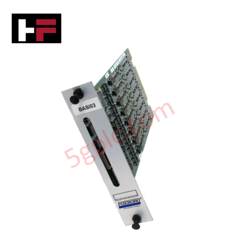
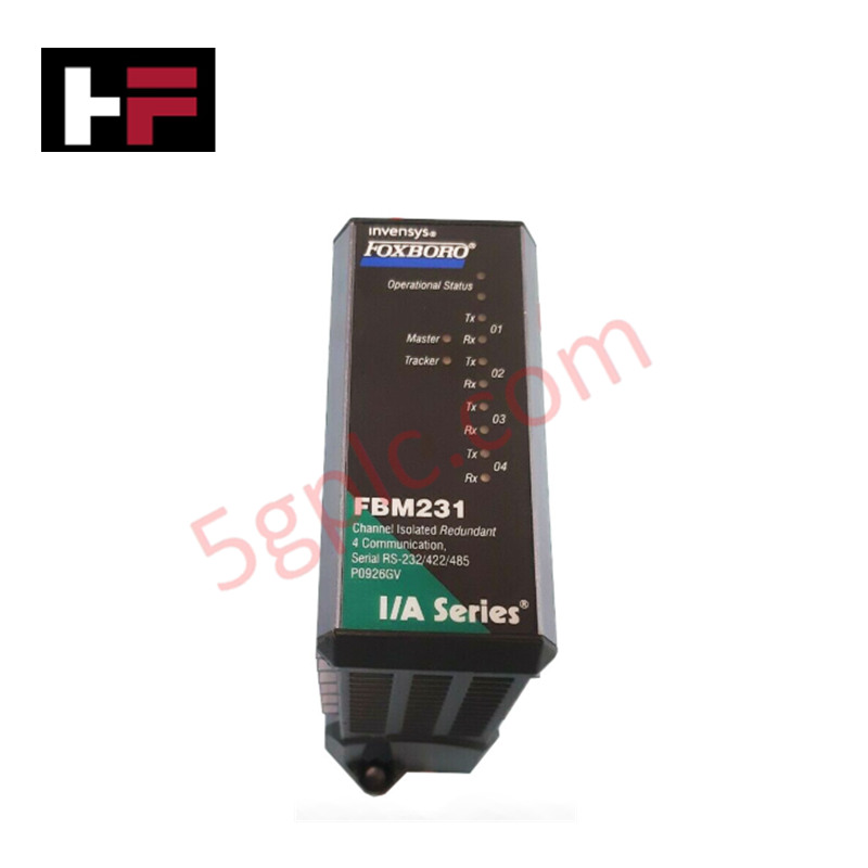
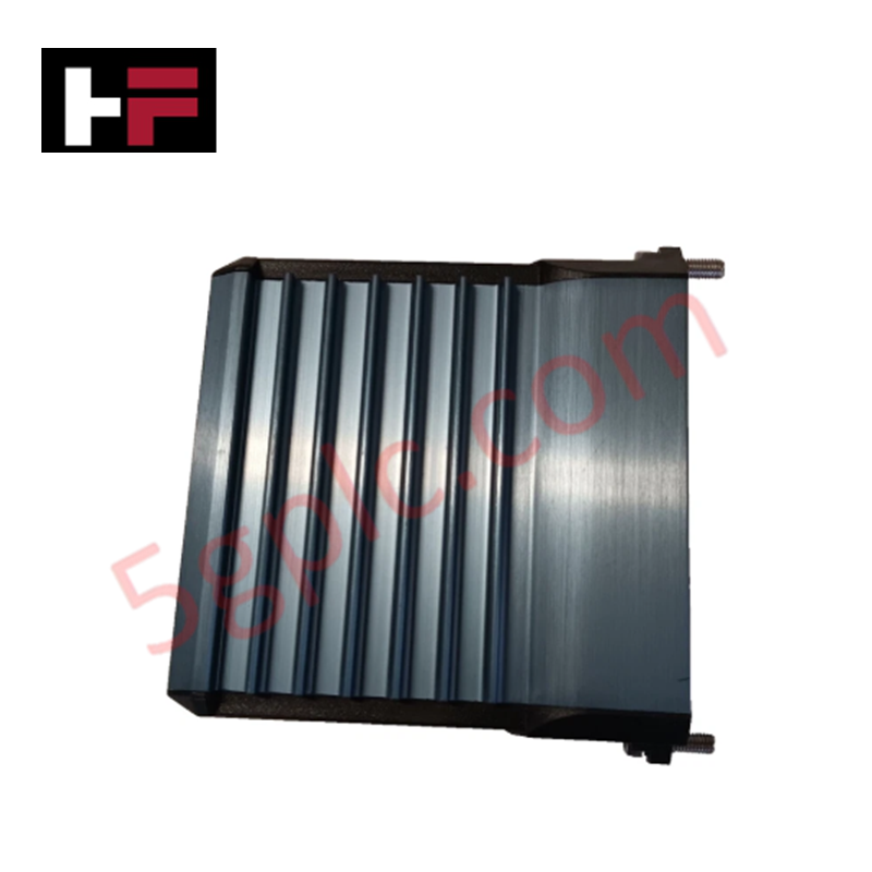
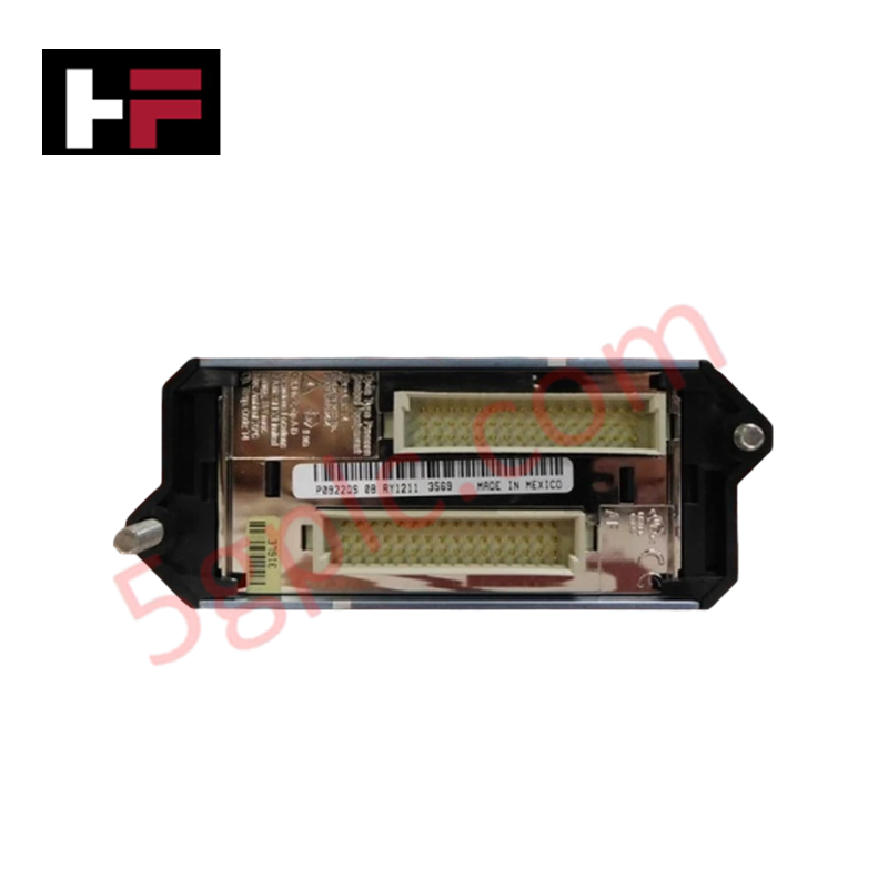
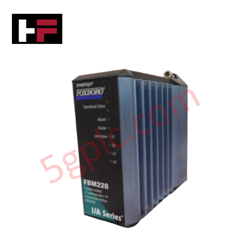
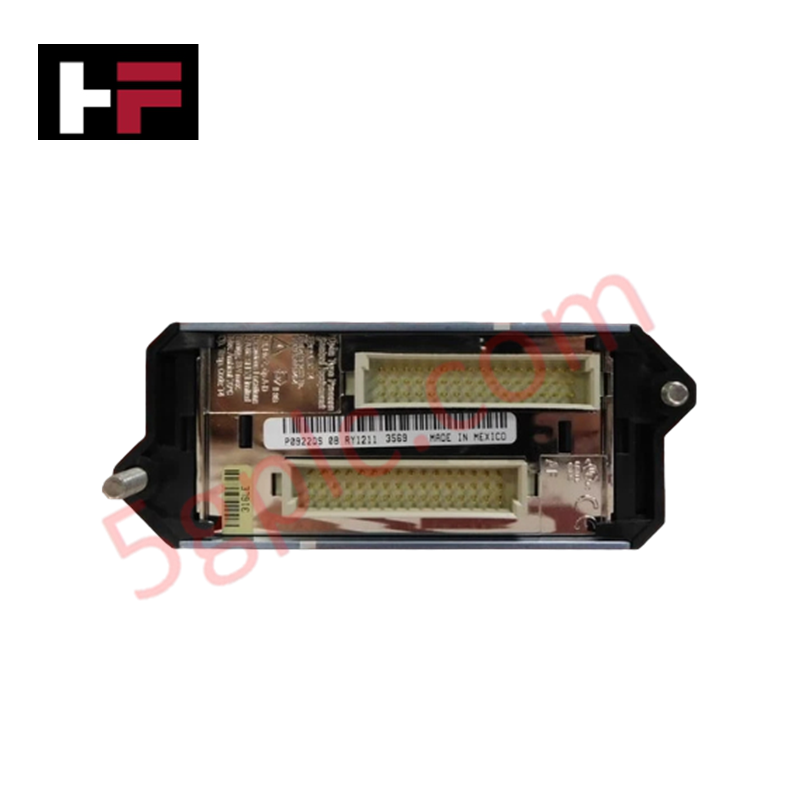
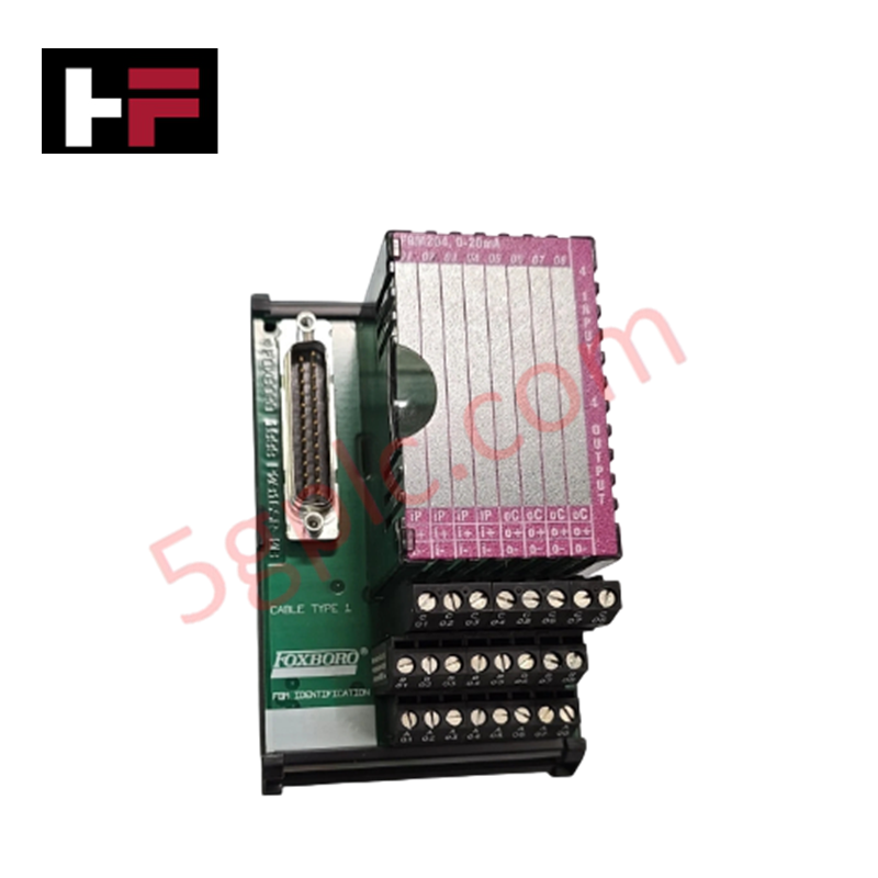
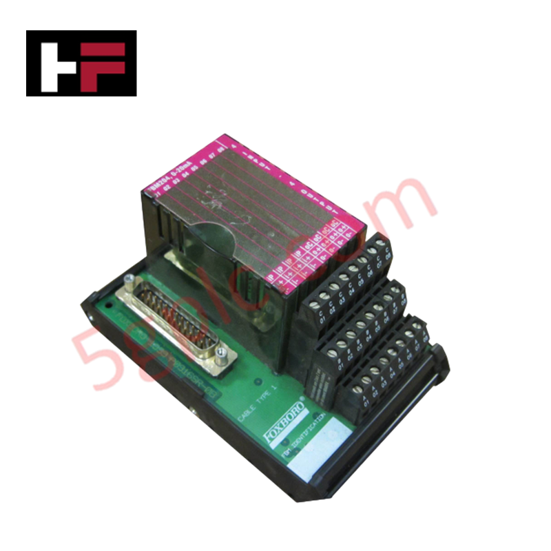
Configured for deterministic real-time control execution and node communication processing in I/A Series DCS networks, the Foxboro P0961BC (CP40B Control Processor Module) provides direct physical/electrical execution. It executes regulatory, discrete, sequential, and advanced control algorithms while interfacing with station local area networks (LANs).
Hardware Specifications
| Parameter | Specification |
|---|---|
| Model | P0961BC (CP40B) |
| Brand | Foxboro |
| Origin | USA |
| Weight | 1.2 kg |
| Dimensions | 3.5 cm x 45 cm x 23 cm |
| Processor Type | CP40B Control Processor |
| Operating Temp | 0 to +60 deg C |
| Power Consumption | 15 W |
| System Platform | I/A Series Subsystem Architecture |
Channel-to-Channel Isolation & Loop Protocol Execution
The Foxboro P0961BC control processor processes process variables digitized by fieldbus modules (FBMs), maintaining digital isolation across backplane bus segments. The controller handles high-throughput scan cycles for multi-channel I/O signals, managing 4-20 mA HART loop protocol telemetry pass-through to plant asset management software. Channel-to-channel isolation on associated I/O baseplates prevents ground loop interference from affecting internal control processor bus operations and memory storage integrity.
Frequently Asked Questions
Q: Does the Foxboro P0961BC module support redundant processor tracking and bumpless failover?
A: Yes, when deployed in a dual-processor baseplate slot configuration, the P0961BC executes continuous state synchronization across dedicated high-speed bus links to support bumpless control transfer upon primary unit fault detection.
Q: How is operating system and control block firmware updated on the CP40B processor?
A: Firmware flash compatibility allows software image loading over the system bus using I/A Series system management utilities without physical EPROM replacement.
Field Installation Guidelines
- Verify system baseplate power supplies are within operating limits before inserting the P0961BC module into its assigned processor slot.
- Ensure ESD grounding wrist straps are attached prior to handling the module circuit board assembly.
- Align the module edge connector with the baseplate guide rails and push firmly until the faceplate latches engage.
- Fasten top and bottom retaining screws hand-tight to secure the mechanical ground connection to the enclosure rack.
- Connect dedicated network interface cabling to the primary and secondary communication ports, confirming redundant channel isolation.
Additional Information
- 100% Genuine Parts: All products are original and authentic, ensuring reliable industrial performance.
- 30-Day Refund Guarantee: Return any in-stock item within 30 days in original, unopened packaging for a full refund (excluding shipping and fees).
- 12-Month Warranty: Covers defects in materials or workmanship; excludes misuse, normal wear, or unauthorized modifications.
- Worldwide Shipping: We ship via USPS, UPS, FedEx, and DHL. Delivery times vary by country and may be subject to customs or import fees.
- Support & Contact: Technical and warranty assistance is available anytime. Contact us here: Contact.
- Purchase Guidance: Check product specifications and compatibility carefully before ordering to ensure proper application.
Tech & Buying Guide

Managed Switch vs. Unmanaged Switch: Industrial Ethernet Architecture

Hot Standby vs. Cold Standby Redundancy in Industrial Automation
System availability determines process safety and productivity in industrial automation. Control engineers deploy redundancy to eliminate single points of failure. This technical guide evaluates Hot Standby vs. Cold Standby architectures, comparing failover speeds, memory sync, cost trade-offs, and field selection criteria.