


Product Details
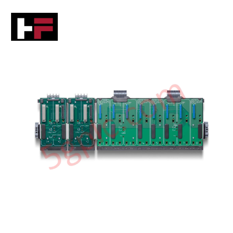
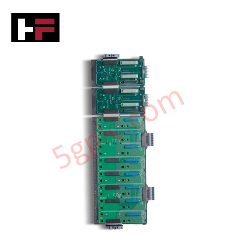
Configured for high-density signal distribution in DeltaV automation networks, the Emerson VE4050E1C0 (VE4050E1C0, also cataloged as KJ4001X1-BE1) 8-wide I/O interface carrier provides direct physical/electrical execution of module-to-backplane interfacing.
Hardware Specifications
| Parameter | Specification |
| Model | VE4050E1C0 |
| Brand | Emerson |
| Origin | USA |
| Weight | Not specified |
| Dimensions | 8-wide slot form factor |
| Operating Temp | Not specified |
| Power Consumption | Supports redundant power inputs |
| Module Capacity | 8 I/O modules |
| Mounting | Standard DIN rail |
Process Control: Channel-to-Channel Isolation
The VE4050E1C0 carrier architecture provides the structural base for system-wide signal processing. It facilitates channel-to-channel isolation by maintaining strict electrical separation between the backplane communication bus and individual I/O module slots. This design ensures that ground potential variations or transient surges present at a single I/O loop connection are contained, preventing propagation to the primary control bus or the associated 4-20 mA HART loop circuits. The carrier incorporates an integrated ground plane that maintains electrical continuity across all 8 slots, providing a robust reference for shielding and common-mode noise suppression during high-speed field signal transmission.
Frequently Asked Questions (FAQ)
Q: Can the carrier support a mix of signal types simultaneously?
A: Yes. The VE4050E1C0 is designed to support a combination of Analog, Discrete, and HART modules across its 8 slots. Note that when utilizing CHARM-specific interfaces, the carrier must be confirmed as compatible with the intended CHARM block configuration to ensure proper pin mapping.
Q: Does the carrier support power redundancy?
A: Yes. The hardware design supports redundant power input configurations. Users must ensure that independent power supply modules are connected to the designated input terminals to maintain system uptime in the event of a single power branch failure.
Field Installation Guidelines
-
Mounting: Secure the carrier onto a standard DIN rail. Ensure the rail is leveled and grounded to the cabinet earth bus to provide the necessary mechanical stability and reference potential for the module ground plane.
-
Grounding: Utilize the integrated terminal bonding points to connect the carrier ground plane to the system earth. Tighten all bonding screws to ensure low-impedance contact, as this is mandatory for maintaining the integrity of the galvanic isolation barriers.
-
Power Wiring: Connect redundant 24 VDC power sources to the input terminals. Verify correct polarity using a digital multimeter before powering the system to avoid potential damage to the internal backplane protection circuitry.
-
Module Seating: Insert modules into the 8 available slots with even pressure. Verify that the backplane connector is fully engaged and that the locking mechanism is secured to prevent intermittent connections due to vibration.
Additional Information
- 100% Genuine Parts: All products are original and authentic, ensuring reliable industrial performance.
- 30-Day Refund Guarantee: Return any in-stock item within 30 days in original, unopened packaging for a full refund (excluding shipping and fees).
- 12-Month Warranty: Covers defects in materials or workmanship; excludes misuse, normal wear, or unauthorized modifications.
- Worldwide Shipping: We ship via USPS, UPS, FedEx, and DHL. Delivery times vary by country and may be subject to customs or import fees.
- Support & Contact: Technical and warranty assistance is available anytime. Contact us here: Contact.
- Purchase Guidance: Check product specifications and compatibility carefully before ordering to ensure proper application.


Tech & Buying Guide

Navigating Industrial Automation Failures: Types, Causes, and Mitigation Strategies
Modern manufacturing relies heavily on automated control systems to maximize throughput and maintain product quality. However, unplanned downtime in industrial automation can cost facility operators thousands of dollars per hour. Understanding how programmable logic controllers (PLCs), distributed control systems (DCS), and field instrumentation fail empowers engineering teams to implement robust preventive maintenance strategies.

Essential Motion Control Commands: A Practical Guide for Engineers
Automation engineers often rely on precise position and speed control to drive modern factory machinery. Modern industrial systems, such as Programmable Logic Controllers (PLCs) and Distributed Control Systems (DCS), depend heavily on standardized motion instructions. Mastering these commands ensures operational safety, protects mechanical components, and optimizes cycle times across production lines.

The Role of Intrinsic Safety Barriers in PLC and DCS Architectures
Implementing robust protection in hazardous industrial environments represents a fundamental safety requirement in factory automation. Process facilities often handle volatile gases, dusts, and chemical agents that pose significant combustion risks. Consequently, control system engineers must deploy energy-limiting interfaces to isolate safe-area control cabinets from hazardous-area field instrumentation. This article examines the function, selection, and electrical principles of intrinsic safety barriers within modern PLC and DCS networks.