


Product Details
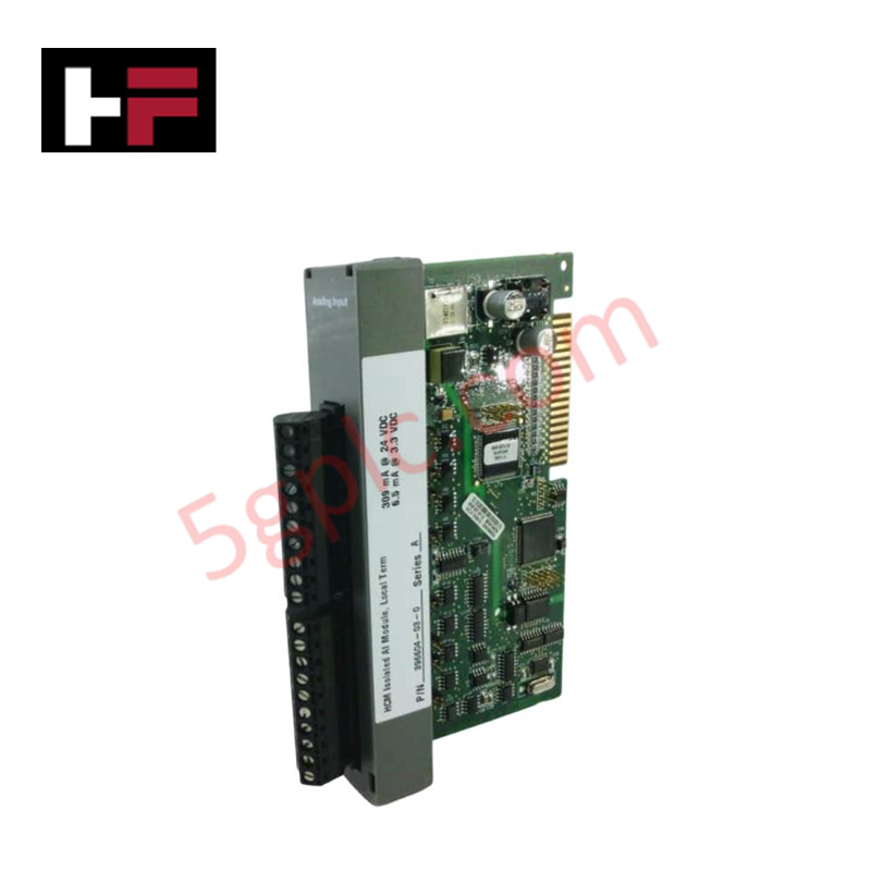
The Emerson 396604-03-0 serves as the primary 396604-03-0 Analog Input/Output Module utilized to execute localized voltage/current data acquisition across ControlWave network platforms. The hardware processes multiple external analog source channels, converting physical instrumentation loop variables into discrete data registers for backplane controller tracking and continuous logic evaluation.
Hardware Specifications
| Parameter | Specification |
| Model | 396604-03-0 |
| Brand | Emerson |
| Origin | USA |
| Weight | 0.33 lbs |
| Dimensions | Standard ControlWave rack chassis slot footprint |
| Operating Temp | -40 deg C to +70 deg C |
| Power Consumption | 309 mA at 24 VDC |
| Channel Count | 8 input channels |
| Isolation Profile | HCM Isolated configuration |
| Subsystem Class | Analog Input/Output infrastructure |
Process Instrumentation Interfaces and Channel-to-Channel Isolation
Mechanical execution of this analog interface utilizes specialized electrical boundaries to maintain signal accuracy across adjacent loop channels. The internal board design utilizes channel-to-channel isolation parameters alongside the integrated HCM isolation circuit. This framework prevents localized ground loops, transient voltage spikes, or high-frequency induction noise from migrating into neighboring paths, preserving data tracking performance across the 4-20 mA HART loop protocol layer connected to the system.
Frequently Asked Questions
Q: Does this analog module support hot-swap removal while the control chassis is energized?
A: No. Extracting or inserting this module while the backplane bus is powered can cause localized logic tracking errors, potential bus faults, or physical component degradation. The system rack power must be completely isolated before attempting card maintenance.
Q: How does the HCM isolation architecture impact field transmitter connections?
A: The High-Channel-to-Channel Isolation (HCM) layout electrically isolates the 8 input paths from each other and the main internal logic rail, reducing measurement distortion caused by ground potential shifts in multi-wire field layouts.
Field Installation Guidelines
-
Chassis Slot Alignment: Insert the card assembly smoothly into the designated slot guides on the control rack base housing. Seat the rear pins entirely into the backplane connectors and tighten the faceplate screws to establish ground continuity.
-
Shield Line Drainage Matrix: Terminate the external analog signal wire shields directly at the cabinet master earth ground bus bar. Using correct single-point grounding methods limits ambient electromagnetic interference from introducing offset drift on standard 4-20 mA inputs.
-
Conductor Routing Separation: Route low-voltage analog signal wires inside separate wire trays away from high-voltage motor supply or power switching lines to prevent magnetic noise induction.
-
Ambient Thermal Tracking: Ensure that enclosure ventilation paths remain unblocked during operational tracking, verifying that the cabinet temperature profile stays within the allowed -40 deg C to +70 deg C window.
Additional Information
- 100% Genuine Parts: All products are original and authentic, ensuring reliable industrial performance.
- 30-Day Refund Guarantee: Return any in-stock item within 30 days in original, unopened packaging for a full refund (excluding shipping and fees).
- 12-Month Warranty: Covers defects in materials or workmanship; excludes misuse, normal wear, or unauthorized modifications.
- Worldwide Shipping: We ship via USPS, UPS, FedEx, and DHL. Delivery times vary by country and may be subject to customs or import fees.
- Support & Contact: Technical and warranty assistance is available anytime. Contact us here: Contact.
- Purchase Guidance: Check product specifications and compatibility carefully before ordering to ensure proper application.


Tech & Buying Guide

Navigating Industrial Automation Failures: Types, Causes, and Mitigation Strategies
Modern manufacturing relies heavily on automated control systems to maximize throughput and maintain product quality. However, unplanned downtime in industrial automation can cost facility operators thousands of dollars per hour. Understanding how programmable logic controllers (PLCs), distributed control systems (DCS), and field instrumentation fail empowers engineering teams to implement robust preventive maintenance strategies.

Essential Motion Control Commands: A Practical Guide for Engineers
Automation engineers often rely on precise position and speed control to drive modern factory machinery. Modern industrial systems, such as Programmable Logic Controllers (PLCs) and Distributed Control Systems (DCS), depend heavily on standardized motion instructions. Mastering these commands ensures operational safety, protects mechanical components, and optimizes cycle times across production lines.

The Role of Intrinsic Safety Barriers in PLC and DCS Architectures
Implementing robust protection in hazardous industrial environments represents a fundamental safety requirement in factory automation. Process facilities often handle volatile gases, dusts, and chemical agents that pose significant combustion risks. Consequently, control system engineers must deploy energy-limiting interfaces to isolate safe-area control cabinets from hazardous-area field instrumentation. This article examines the function, selection, and electrical principles of intrinsic safety barriers within modern PLC and DCS networks.