


Product Details
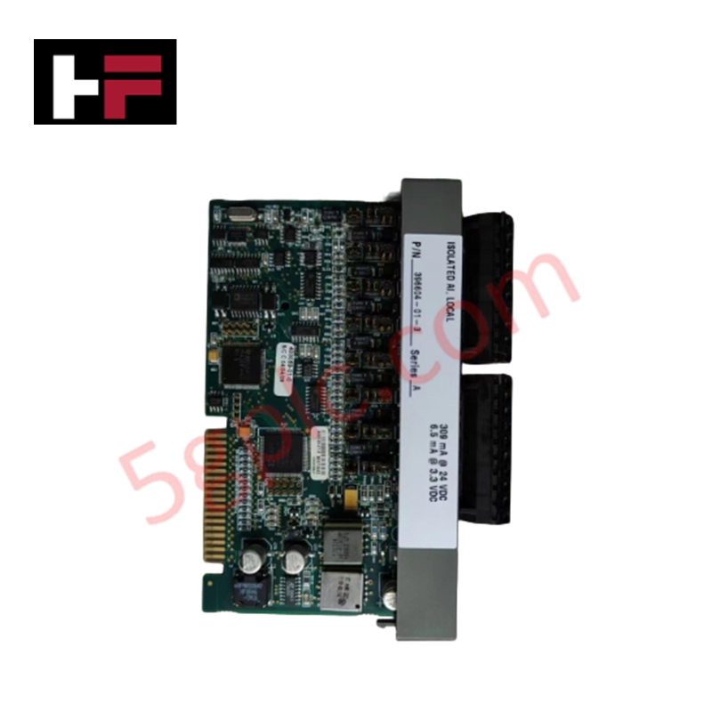
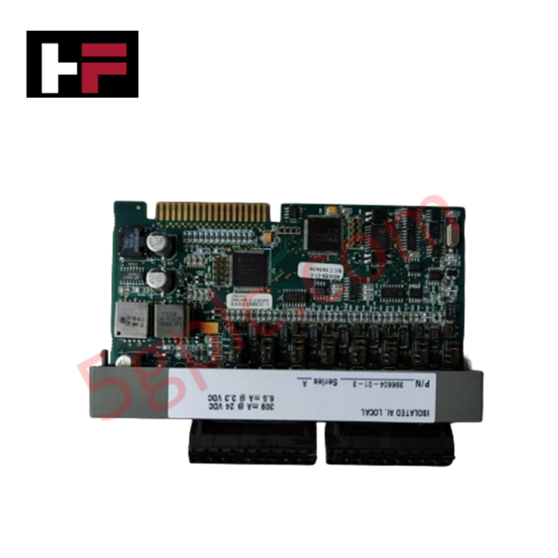
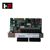
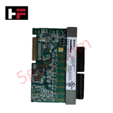
The Emerson 396604-01-3, also cataloged as the 396604-01-3 Analog Input Module, operates as a dedicated hardware component for localized analog signal digitizing and parameter extraction within ControlWave Micro platforms. This component directly monitors external current and voltage loop variables via dedicated screw terminals, converting raw physical telemetry data into processed binary representations across the system local area bus structures.
Hardware Specifications
| Parameter | Specification |
| Model | 396604-01-3 |
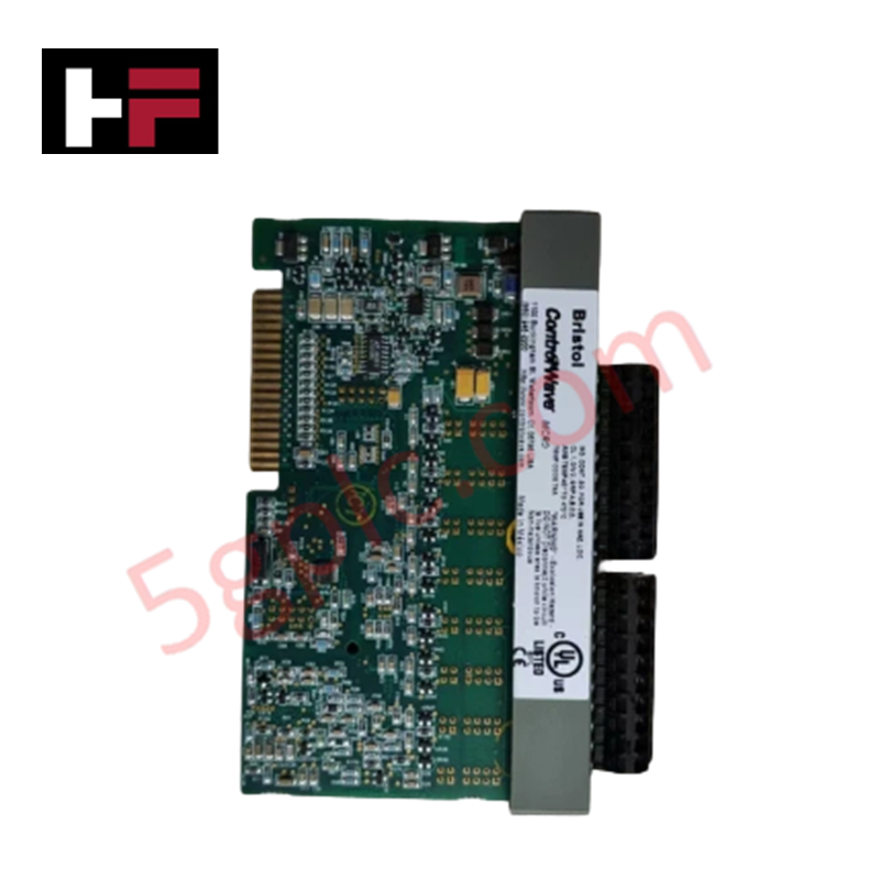
| Brand | Emerson (Bristol) |
| Origin | USA |
| Weight | 10.01 lbs |
| Dimensions | Standard ControlWave Micro rack chassis module footprint |
| Operating Temp | -40 deg C to +70 deg C |
| Power Consumption | 6.5 mA at 3.3 VDC (Logic Bus) and 309 mA at 24 VDC (Field Bus) |
| Physical Interface | Integrated screw terminals |
| Isolation Type | Galvanically isolated circuit pathways |
| Input Density | Multi-channel analog tracking structure |
Channel-To-Channel Isolation Topology
Mechanical execution of this ControlWave interface module relies on galvanic barrier structures implemented directly on each terminal loop track. The hardware enforces rigorous channel-to-channel isolation methods to decouple individual incoming field measurement lines from adjacent circuits and the inner processing backplane. This structural segregation prevents common-mode voltage offsets, electrical noise spikes, or accidental field ground loops from degrading parallel loops, preserving 4-20 mA HART loop protocol layer integrity across the operational spectrum.
Frequently Asked Questions
Q: Can this analog input module undergo live replacement routines while the rack chassis is powered?
A: No. Electrical power to the ControlWave Micro baseplate must be fully isolated before extracting or inserting the module. Live modification risks inducing logic bus disruptions or causing circuit failure on the active 3.3 VDC track.
Q: What are the independent current requirements across the dual voltage rails of this hardware?
A: The module splits its load, demanding 6.5 mA at 3.3 VDC to supply the internal analog-to-digital converter logic and a separate 309 mA at 24 VDC to energize the isolated loop conditioning circuits.
Field Installation Guidelines
-
Module Alignment and Seating: Slide the assembly into the target slot of the ControlWave Micro carrier chassis along the top and bottom guide rails. Push the unit inward until the rear pins mesh with the backplane distribution assembly.
-
Screw Terminal Termination: Strip input wire jackets down to factory specification. Secure each conductor within the integrated screw terminals, checking that the clamping terminal screws are torqued down completely to maintain low path resistance.
-
Shield Ground Maintenance: Terminate all instrumentation cable shield conductors exclusively at the centralized marshalling panel common ground bus bar. A single-point grounding matrix must be verified to inhibit circulating currents from altering sensor measurements.
-
Environmental Enclosure Management: Keep this module assembly inside a weather-tight, dust-free industrial cabinet. Check that continuous ambient ventilation limits internal humidity parameters below the non-condensing tracking window.
Additional Information
- 100% Genuine Parts: All products are original and authentic, ensuring reliable industrial performance.
- 30-Day Refund Guarantee: Return any in-stock item within 30 days in original, unopened packaging for a full refund (excluding shipping and fees).
- 12-Month Warranty: Covers defects in materials or workmanship; excludes misuse, normal wear, or unauthorized modifications.
- Worldwide Shipping: We ship via USPS, UPS, FedEx, and DHL. Delivery times vary by country and may be subject to customs or import fees.
- Support & Contact: Technical and warranty assistance is available anytime. Contact us here: Contact.
- Purchase Guidance: Check product specifications and compatibility carefully before ordering to ensure proper application.


Tech & Buying Guide

Navigating Industrial Automation Failures: Types, Causes, and Mitigation Strategies
Modern manufacturing relies heavily on automated control systems to maximize throughput and maintain product quality. However, unplanned downtime in industrial automation can cost facility operators thousands of dollars per hour. Understanding how programmable logic controllers (PLCs), distributed control systems (DCS), and field instrumentation fail empowers engineering teams to implement robust preventive maintenance strategies.

Essential Motion Control Commands: A Practical Guide for Engineers
Automation engineers often rely on precise position and speed control to drive modern factory machinery. Modern industrial systems, such as Programmable Logic Controllers (PLCs) and Distributed Control Systems (DCS), depend heavily on standardized motion instructions. Mastering these commands ensures operational safety, protects mechanical components, and optimizes cycle times across production lines.

The Role of Intrinsic Safety Barriers in PLC and DCS Architectures
Implementing robust protection in hazardous industrial environments represents a fundamental safety requirement in factory automation. Process facilities often handle volatile gases, dusts, and chemical agents that pose significant combustion risks. Consequently, control system engineers must deploy energy-limiting interfaces to isolate safe-area control cabinets from hazardous-area field instrumentation. This article examines the function, selection, and electrical principles of intrinsic safety barriers within modern PLC and DCS networks.