


Product Details
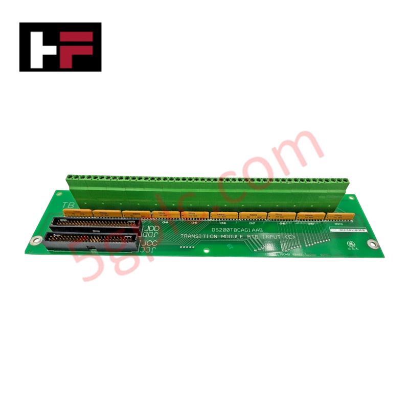
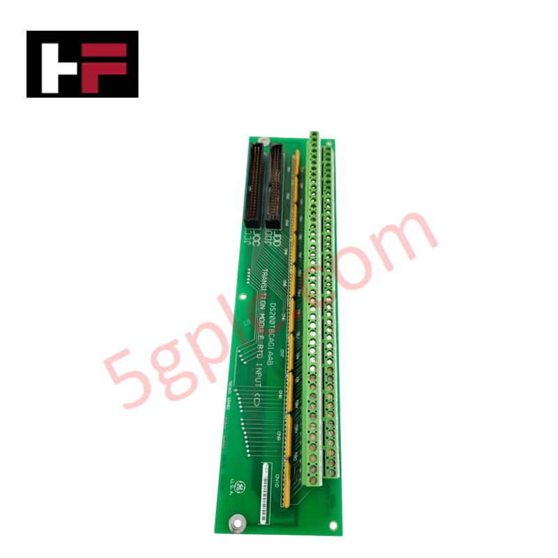
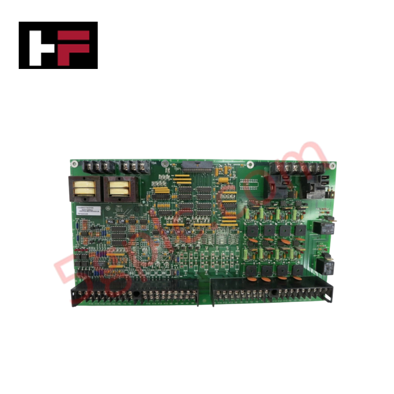
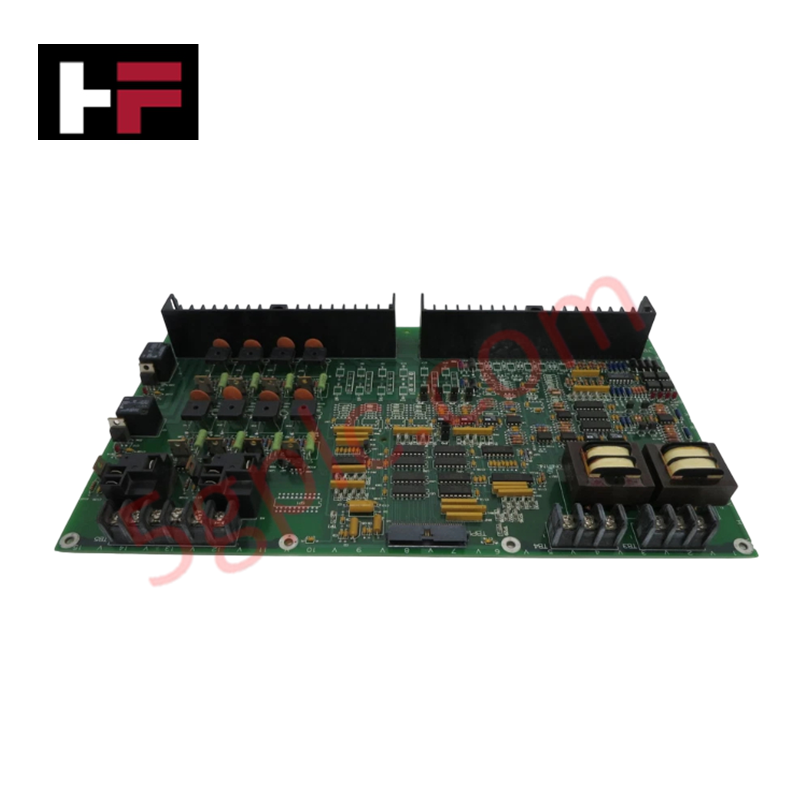
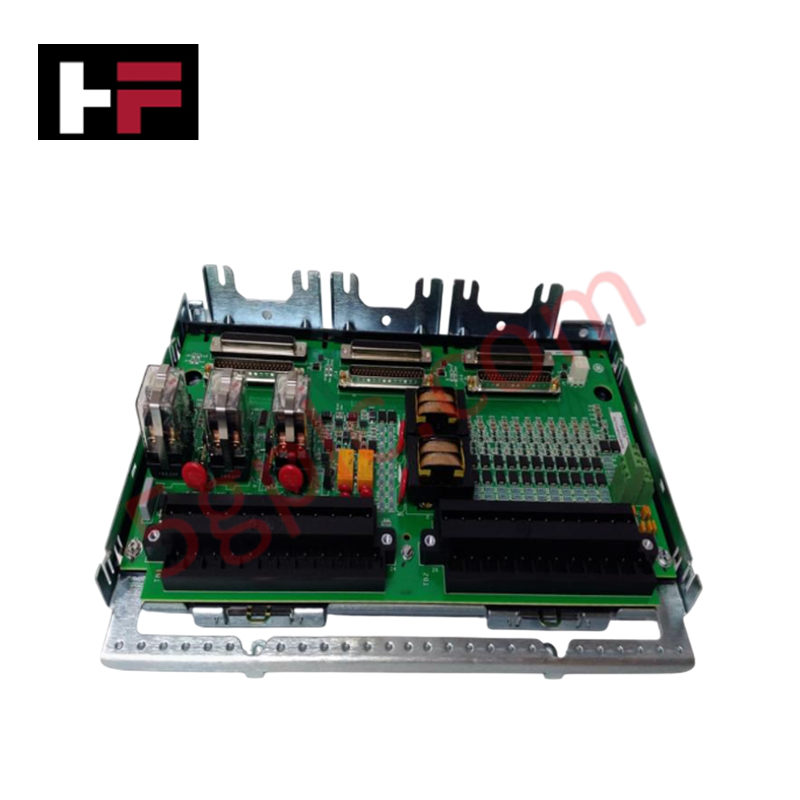
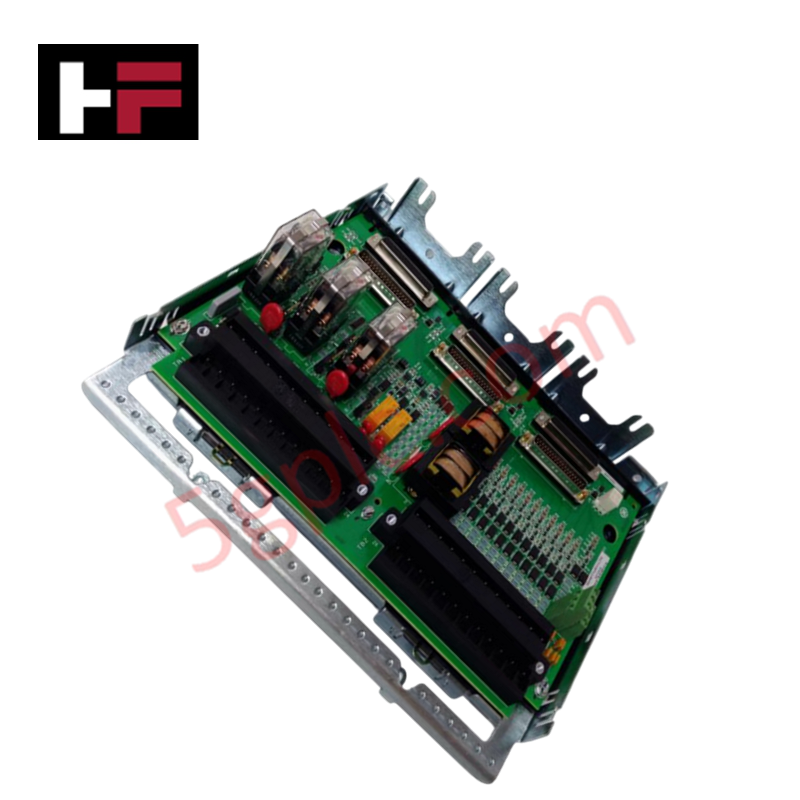
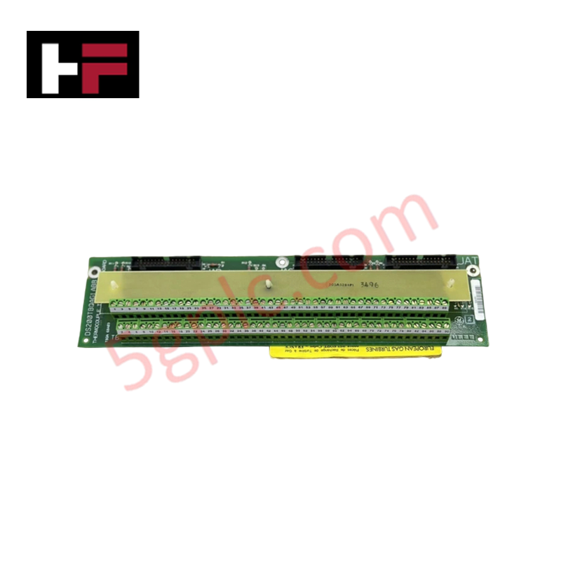
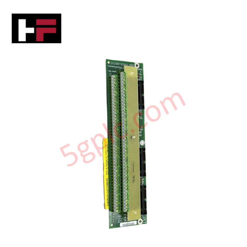
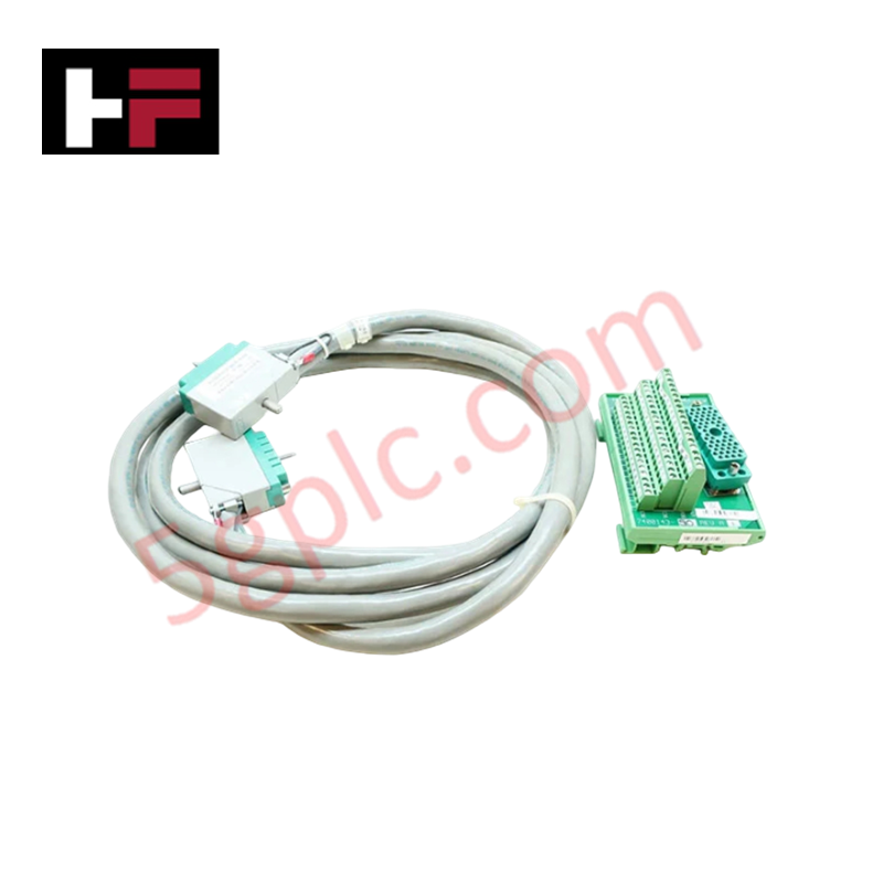
The GE DS200TBCAG1A, also cataloged as the DS200TBCA Terminal Board, operates as a dedicated hardware component for interfacing Resistance Temperature Detector (RTD) sensors to TCCA control boards within Mark V LM turbine management platforms.
Hardware Specifications
| Parameter | Specification |
|---|---|
| Model | DS200TBCAG1A |
| Brand | GE (General Electric) |
| Origin | USA |
| Operating Temp | -20 deg C to 70 deg C |
| Power Consumption | 100-500 mA |
| Input Channels | 4 to 16 channels |
| Sensor Support | PT100, PT1000 RTD types |
| Output Signal | 0-10 V, 4-20 mA |
| Operating Voltage | 24 VDC |
Deterministic Network and Control Compatibility
The DS200TBCAG1A facilitates signal conditioning by converting resistive fluctuations from RTD sensors into standardized analog outputs. Within the Mark V LM architecture, this board maintains synchronization with the R5 core control loop. Deterministic performance is contingent upon the backplane bus communication velocity established between the TBCA and the linked TCCA board. Firmware flash compatibility is managed at the TCCA level; ensure that the host control software is configured to interpret the specific channel density of the terminal board to prevent data acquisition latencies or conversion errors in the turbine control sequence.
Frequently Asked Questions
Q: Is this terminal board capable of hot-swapping while the R5 core is active?
A: No. Any interaction with the terminal connections or the board itself must occur during a scheduled system shutdown. Hot-swapping the board risks interrupting the measurement feedback loop, which will trigger a diagnostic fault or a protective trip in the turbine control system.
Q: How should shielded cables be terminated to ensure signal integrity?
A: Shielded cables must be terminated to the designated grounding terminals on the board assembly. Ensure the shield is grounded at one end only, following standard site grounding practices, to prevent ground loops that could introduce noise into the 4-20 mA or 0-10 V measurement signals.
Field Installation Guidelines
- Terminal Wiring: When connecting RTD sensors, ensure that leads are properly secured to the screw terminals. Verify that the wire gauge is compatible with the terminal block capacity to maintain low-resistance contacts.
- Sensor Calibration: After installation, confirm the RTD type (PT100 or PT1000) matches the software configuration in the Mark V control system to ensure accurate resistance-to-temperature correlation.
- Environment: Install the board in a climate-controlled cabinet to ensure ambient temperatures remain within the -20 deg C to 70 deg C range. Avoid locations subject to high vibration or excessive electromagnetic interference from high-power cabling.
- Verification: Prior to system startup, measure the loop resistance and verify that the 24 VDC power input is within the specified operating limits to prevent thermal stress on the conversion circuitry.
Additional Information
- 100% Genuine Parts: All products are original and authentic, ensuring reliable industrial performance.
- 30-Day Refund Guarantee: Return any in-stock item within 30 days in original, unopened packaging for a full refund (excluding shipping and fees).
- 12-Month Warranty: Covers defects in materials or workmanship; excludes misuse, normal wear, or unauthorized modifications.
- Worldwide Shipping: We ship via USPS, UPS, FedEx, and DHL. Delivery times vary by country and may be subject to customs or import fees.
- Support & Contact: Technical and warranty assistance is available anytime. Contact us here: Contact.
- Purchase Guidance: Check product specifications and compatibility carefully before ordering to ensure proper application.

Tech & Buying Guide

Essential SCADA Features for Modern IoT-Enabled Industrial Automation
The convergence of traditional SCADA systems with the Industrial Internet of Things (IIoT) has redefined factory automation. Choosing a robust platform requires more than just standard monitoring capabilities. In this era of Industry 4.0, your supervisory system must bridge the gap between legacy control systems and enterprise-level data integration.

Selecting Rockwell Automation Allen-Bradley PLCs for Small and Mid-Sized Applications
Rockwell Automation remains a cornerstone in global industrial automation. Their Allen-Bradley brand provides a comprehensive portfolio of control systems designed to meet diverse production requirements. Choosing the right programmable logic controller (PLC) is critical for system reliability and scalability. This guide analyzes the Micro and Compact Logix families to help you select the optimal solution for small and medium-scale projects.

Strategic Selection: Choosing the Right SCADA Software for Your PLC Project
In industrial automation, the SCADA (Supervisory Control and Data Acquisition) system acts as the bridge between raw machine data and actionable human intelligence. Selecting the incorrect software platform can lead to integration bottlenecks, scalability issues, and excessive long-term maintenance costs. As an automation consultant with 15 years of experience, I have guided many projects through the selection process. Below are the essential criteria for choosing a platform that ensures both performance and longevity.