


Product Details
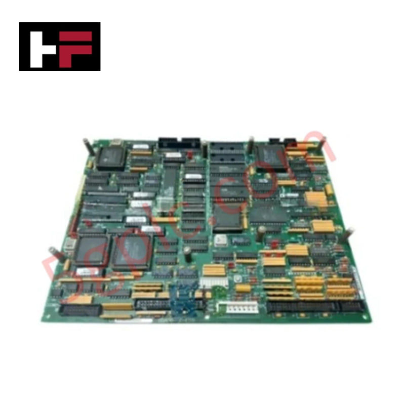
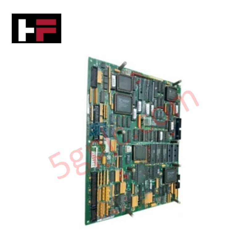
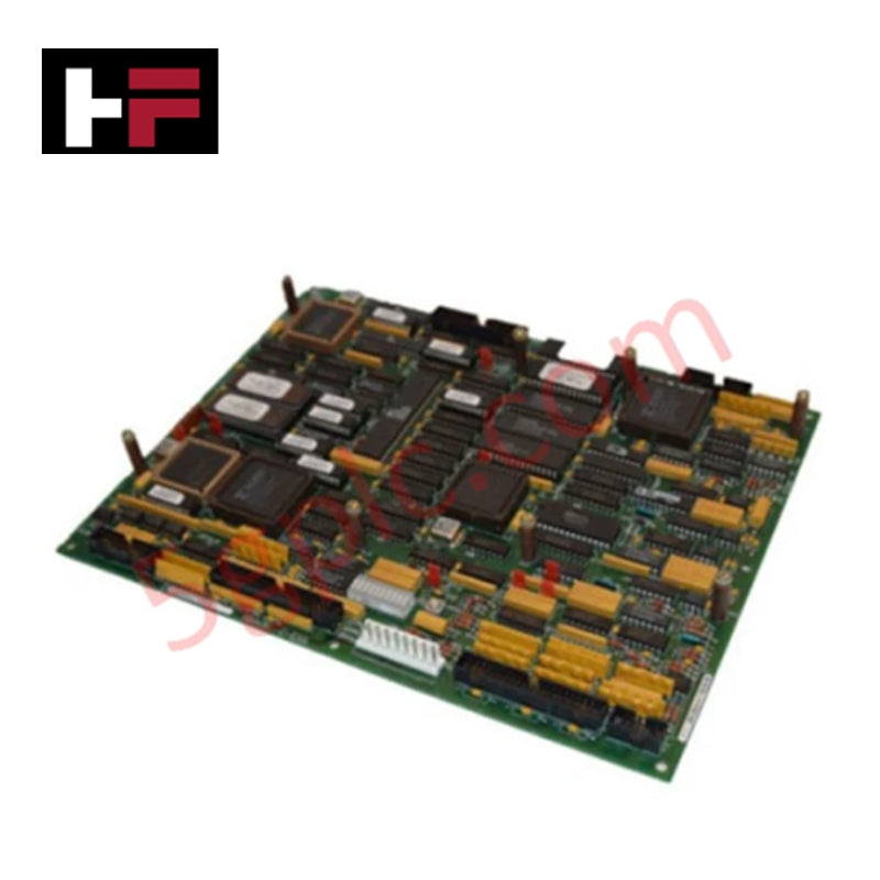
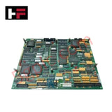
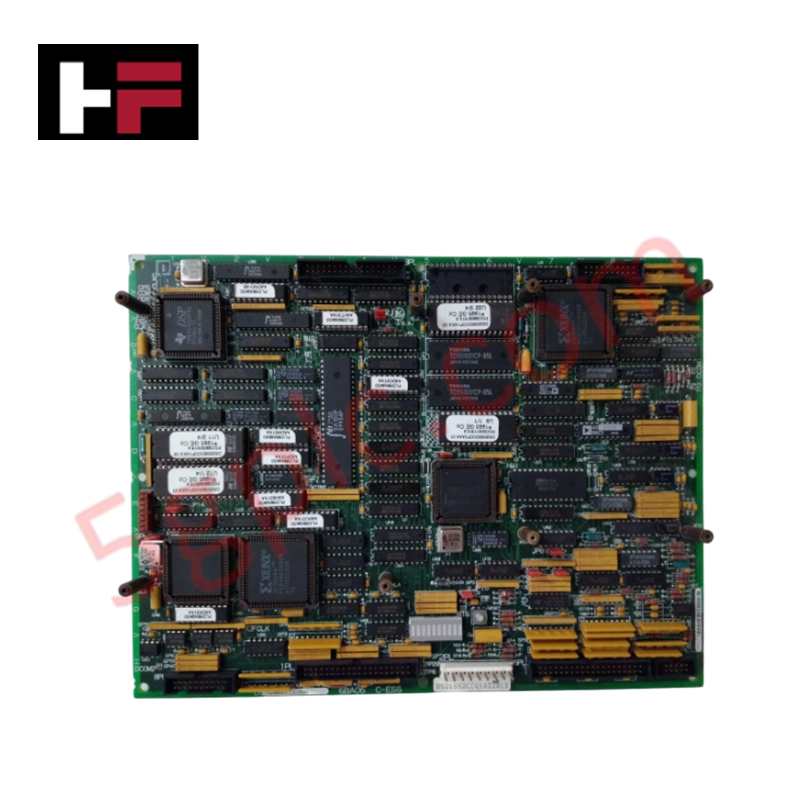
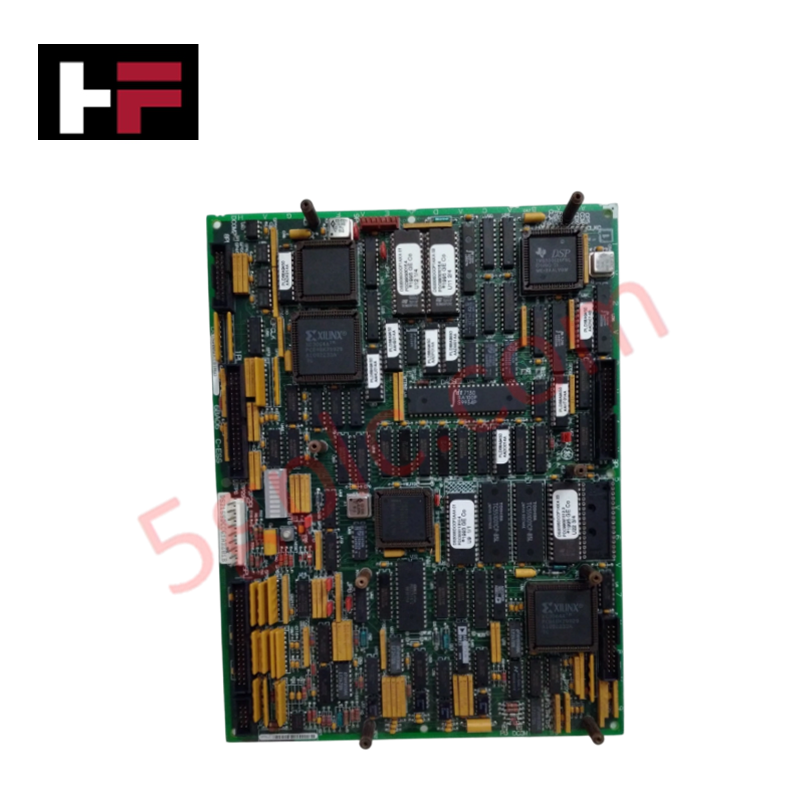
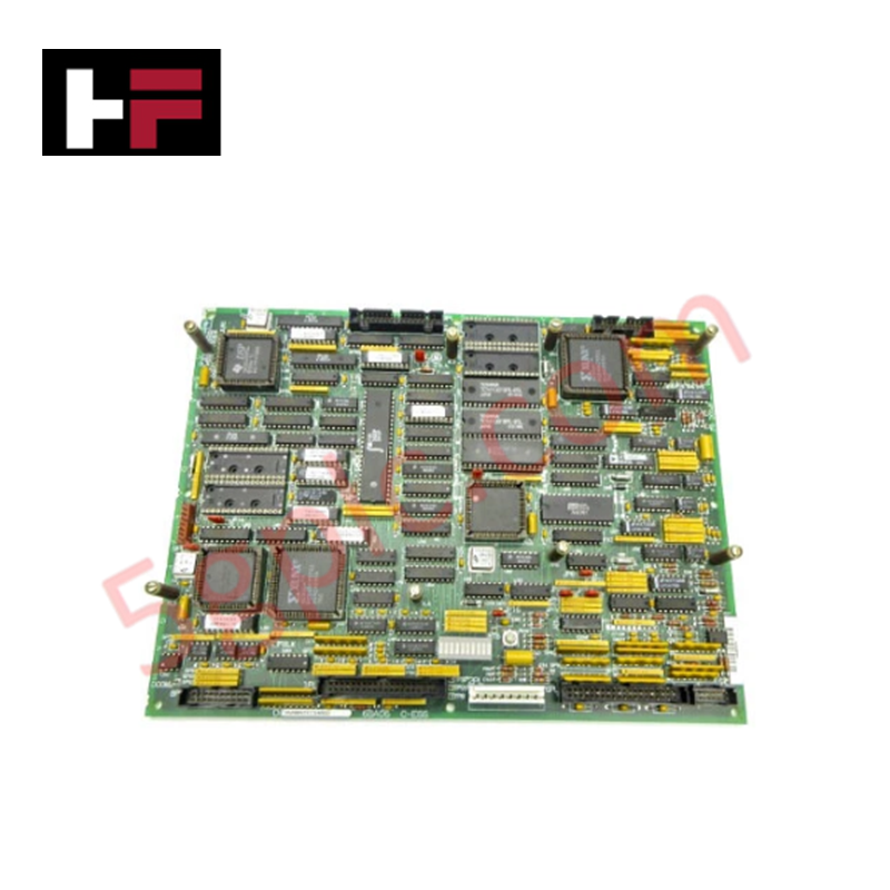
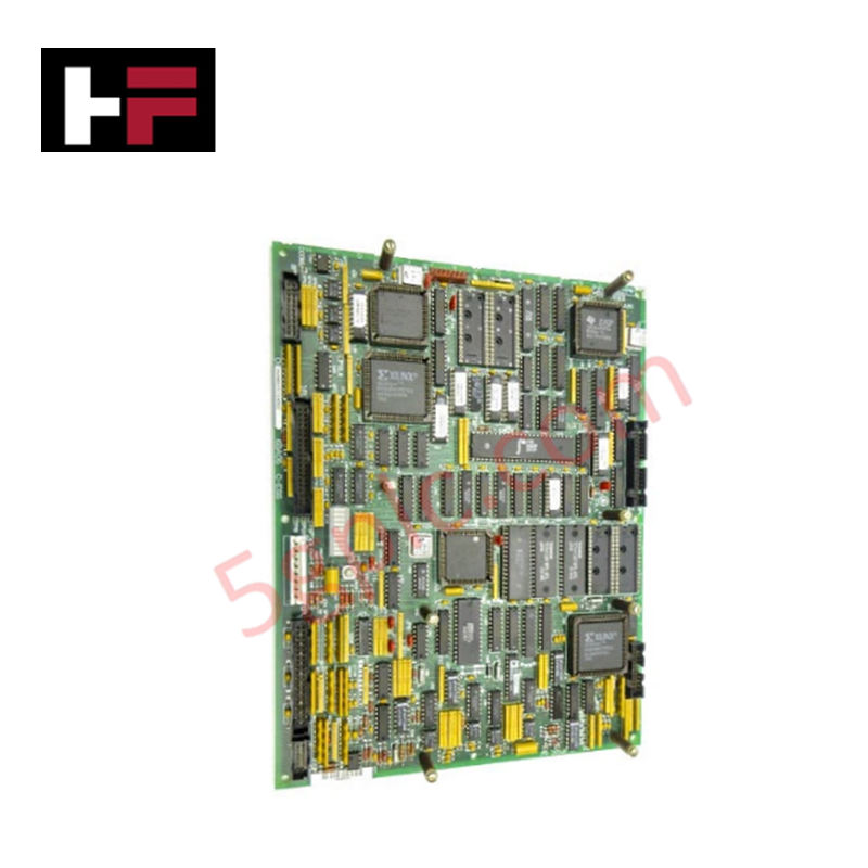
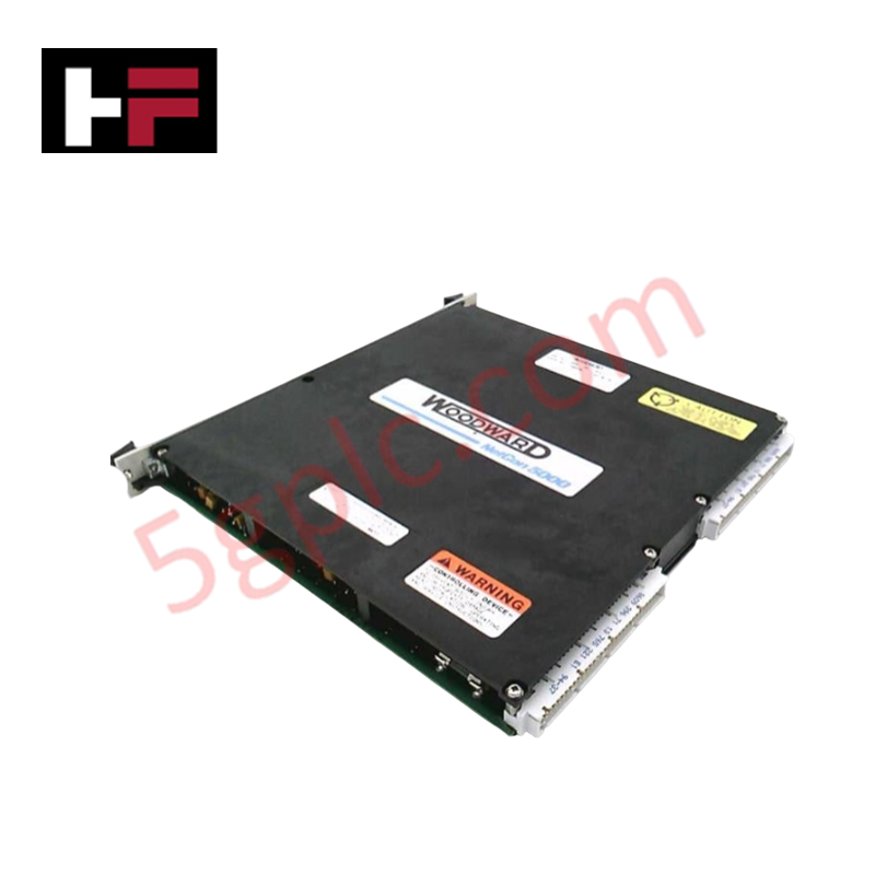
Configured for motion control and signal processing within TC2000 and Mark V turbine control platforms, the General Electric DS200SDCCG5A (DS200SDCCG5 Drive Control Card) provides direct physical/electrical execution.
Hardware Specifications
| Parameter | Specification |
|---|---|
| Model | DS200SDCCG5A |
| Brand | General Electric |
| Origin | USA |
| Weight | 1.5 lb |
| Dimensions | Standard Mark V PCB footprint |
| Operating Temp | Per Mark V environmental requirements |
| Power Consumption | Backplane rail supply |
| Processing | 3 x microprocessors with shared RAM |
| Configuration | 5 x EPROM slots (4 factory, 1 user) |
Industrial Control and Firmware Compatibility
The DS200SDCCG5A utilizes a multi-processor architecture to execute deterministic drive control tasks. The card requires precise firmware flash compatibility; the software stored on the EPROM modules (U11, U12, U22, U23, U9) must be matched to the host system requirements to ensure stable operation. It supports I/O density scaling through the integration of auxiliary boards, which connect via dedicated standoffs and ribbon cables to expand signal processing capabilities or enable network connectivity. Backplane bus communication velocity is fixed by factory-set jumpers; these must remain in their original positions to maintain the deterministic timing required for co-motor control math calculations.
Frequently Asked Questions
Q: Can the factory-set jumpers be reconfigured to change board behavior?
A: No. Jumpers on the DS200SDCCG5A are set at the factory to define specific board address and bus configurations. Altering these settings will result in unpredictable drive behavior or communication faults.
Q: Is this card compatible with all Mark V auxiliary boards?
A: The card includes standard interface connectors and standoffs for auxiliary board mounting. Compatibility is limited to modules specifically designed for the TC2000/Mark V SDCC interface. Refer to manual GEI-100029C for supported auxiliary part numbers.
Field Installation Guidelines
- Static Discharge Protection: The board contains highly sensitive microprocessor and memory components. Always wear a grounded anti-static wrist strap when handling the PCB.
- Auxiliary Mounting: When installing auxiliary cards, use the provided standoffs to ensure mechanical stability. Tighten screws to the specified torque to prevent vibration-induced intermittent connections.
- Cable Seating: Verify that all ribbon cable connectors are fully seated and latched. Misaligned pins can lead to bus communication errors or damage to the microprocessor interface.
- Firmware Integrity: When replacing or updating EPROM modules, ensure correct orientation (notch alignment) to prevent shorting the address or data bus lines.
- Mounting: Secure the board into the Mark V rack using the front panel screws. Ensure the backplane connector is fully engaged before applying power to the drive assembly.
Additional Information
- 100% Genuine Parts: All products are original and authentic, ensuring reliable industrial performance.
- 30-Day Refund Guarantee: Return any in-stock item within 30 days in original, unopened packaging for a full refund (excluding shipping and fees).
- 12-Month Warranty: Covers defects in materials or workmanship; excludes misuse, normal wear, or unauthorized modifications.
- Worldwide Shipping: We ship via USPS, UPS, FedEx, and DHL. Delivery times vary by country and may be subject to customs or import fees.
- Support & Contact: Technical and warranty assistance is available anytime. Contact us here: Contact.
- Purchase Guidance: Check product specifications and compatibility carefully before ordering to ensure proper application.
Tech & Buying Guide

Essential SCADA Features for Modern IoT-Enabled Industrial Automation
The convergence of traditional SCADA systems with the Industrial Internet of Things (IIoT) has redefined factory automation. Choosing a robust platform requires more than just standard monitoring capabilities. In this era of Industry 4.0, your supervisory system must bridge the gap between legacy control systems and enterprise-level data integration.

Selecting Rockwell Automation Allen-Bradley PLCs for Small and Mid-Sized Applications
Rockwell Automation remains a cornerstone in global industrial automation. Their Allen-Bradley brand provides a comprehensive portfolio of control systems designed to meet diverse production requirements. Choosing the right programmable logic controller (PLC) is critical for system reliability and scalability. This guide analyzes the Micro and Compact Logix families to help you select the optimal solution for small and medium-scale projects.

Strategic Selection: Choosing the Right SCADA Software for Your PLC Project
In industrial automation, the SCADA (Supervisory Control and Data Acquisition) system acts as the bridge between raw machine data and actionable human intelligence. Selecting the incorrect software platform can lead to integration bottlenecks, scalability issues, and excessive long-term maintenance costs. As an automation consultant with 15 years of experience, I have guided many projects through the selection process. Below are the essential criteria for choosing a platform that ensures both performance and longevity.