


Product Details
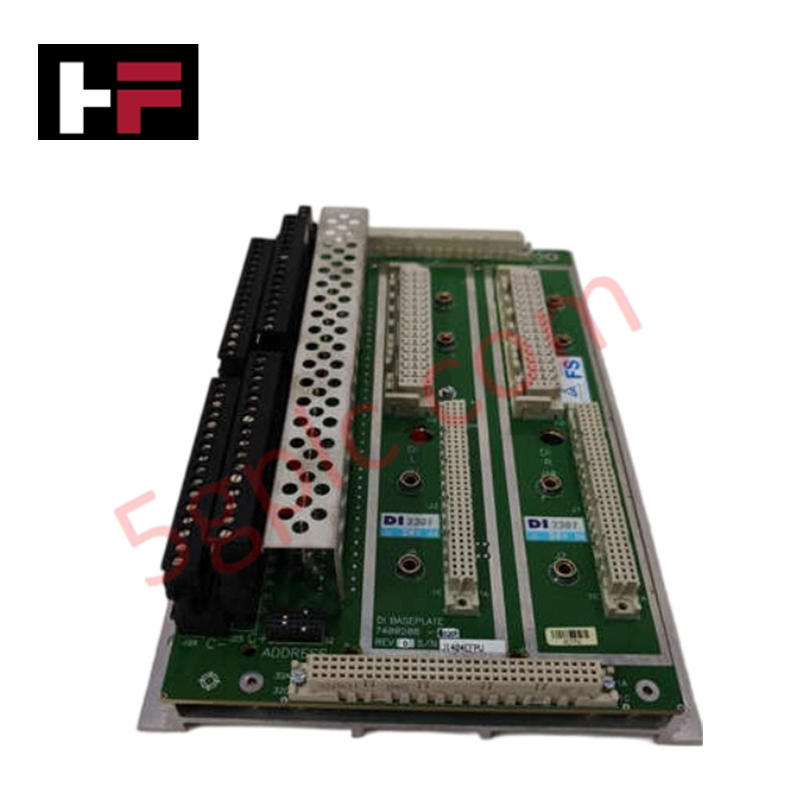
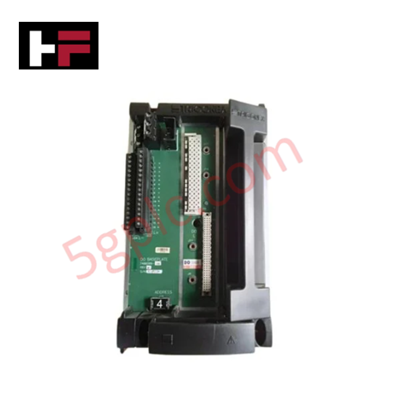
Configured for discrete signal acquisition in safety-instrumented system platforms, the Triconex DI2301 7400208C-020 (DI2301 Digital Input Module) provides direct physical execution of field-to-logic state transition monitoring.
Hardware Specifications
| Parameter | Specification |
|---|---|
| Model | DI2301 7400208C-020 |
| Brand | Triconex |
| Dimensions | Standard 3U rack-mount module |
| Operating Temp | -40 deg C to +70 deg C |
| Power Consumption | Not specified |
| Channels | 16 discrete digital inputs |
| Isolation | 500 V |
High-Reliability Safety Control and SIS Characteristics
The DI2301 module is designed for operation within Triconex triple modular redundancy (TMR) 2oo3 architecture, ensuring continuous signal integrity and fault tolerance for safety-critical inputs. The module features galvanically isolated input channels rated for 500 V, providing effective protection against ground loops and common-mode transients. Furthermore, the internal circuitry incorporates surge protection limits up to 1500 V to enhance resilience in electromagnetically noisy industrial environments. The module supports hot-swap capability, allowing for replacement without interrupting the system operation, provided the installation adheres to the defined safety logic requirements and TMR fault-tolerant protocols.
Frequently Asked Questions
Q: Can the DI2301 module be installed in any slot within the Tricon chassis?
A: The DI2301 must be matched with the corresponding baseplate (7400208C-020). While it is compatible with standard Tricon main or extension chassis, module placement must follow the system design documentation to ensure correct I/O mapping and TMR functionality.
Q: Is the DI2301 compatible with other module types in the same chassis?
A: Yes. The DI2301 can be integrated into the same cabinet and chassis alongside other Tricon modules, such as AI2351 or DO2401, to build a complete I/O subsystem.
Field Installation Guidelines
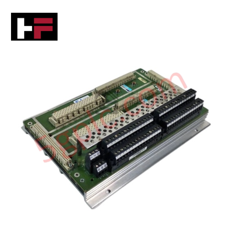
- Verify that the 7400208C-020 baseplate is securely mounted in the 3U rack and properly grounded before module insertion.
- Inspect the rear connector pins on the DI2301 module for any signs of physical obstruction or oxidation.
- Slide the module along the chassis guides until the locking latches engage, ensuring a firm electrical connection with the backplane.
- Verify field wiring terminations at the baseplate terminal blocks, ensuring that the 24 VDC loop configuration matches the input channel requirements.
- Utilize the system diagnostic software to confirm that the input states are being correctly acquired and processed by the CPU after installation.
Additional Information
- 100% Genuine Parts: All products are original and authentic, ensuring reliable industrial performance.
- 30-Day Refund Guarantee: Return any in-stock item within 30 days in original, unopened packaging for a full refund (excluding shipping and fees).
- 12-Month Warranty: Covers defects in materials or workmanship; excludes misuse, normal wear, or unauthorized modifications.
- Worldwide Shipping: We ship via USPS, UPS, FedEx, and DHL. Delivery times vary by country and may be subject to customs or import fees.
- Support & Contact: Technical and warranty assistance is available anytime. Contact us here: Contact.
- Purchase Guidance: Check product specifications and compatibility carefully before ordering to ensure proper application.

Tech & Buying Guide

Essential SCADA Features for Modern IoT-Enabled Industrial Automation
The convergence of traditional SCADA systems with the Industrial Internet of Things (IIoT) has redefined factory automation. Choosing a robust platform requires more than just standard monitoring capabilities. In this era of Industry 4.0, your supervisory system must bridge the gap between legacy control systems and enterprise-level data integration.

Selecting Rockwell Automation Allen-Bradley PLCs for Small and Mid-Sized Applications
Rockwell Automation remains a cornerstone in global industrial automation. Their Allen-Bradley brand provides a comprehensive portfolio of control systems designed to meet diverse production requirements. Choosing the right programmable logic controller (PLC) is critical for system reliability and scalability. This guide analyzes the Micro and Compact Logix families to help you select the optimal solution for small and medium-scale projects.

Strategic Selection: Choosing the Right SCADA Software for Your PLC Project
In industrial automation, the SCADA (Supervisory Control and Data Acquisition) system acts as the bridge between raw machine data and actionable human intelligence. Selecting the incorrect software platform can lead to integration bottlenecks, scalability issues, and excessive long-term maintenance costs. As an automation consultant with 15 years of experience, I have guided many projects through the selection process. Below are the essential criteria for choosing a platform that ensures both performance and longevity.