










Product Details
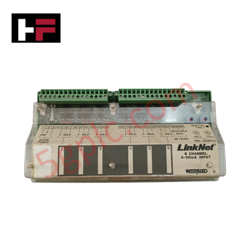
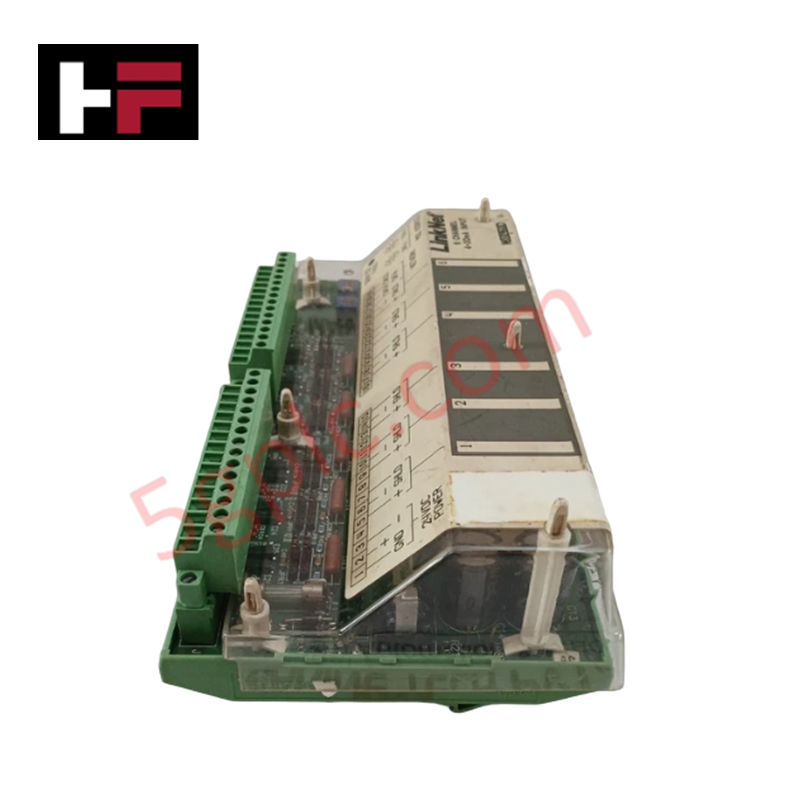
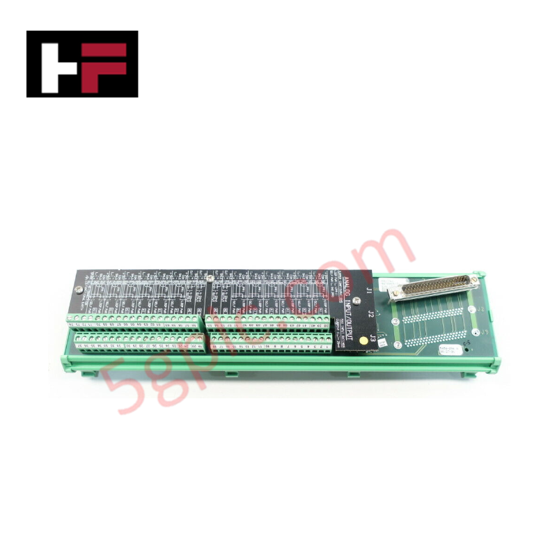
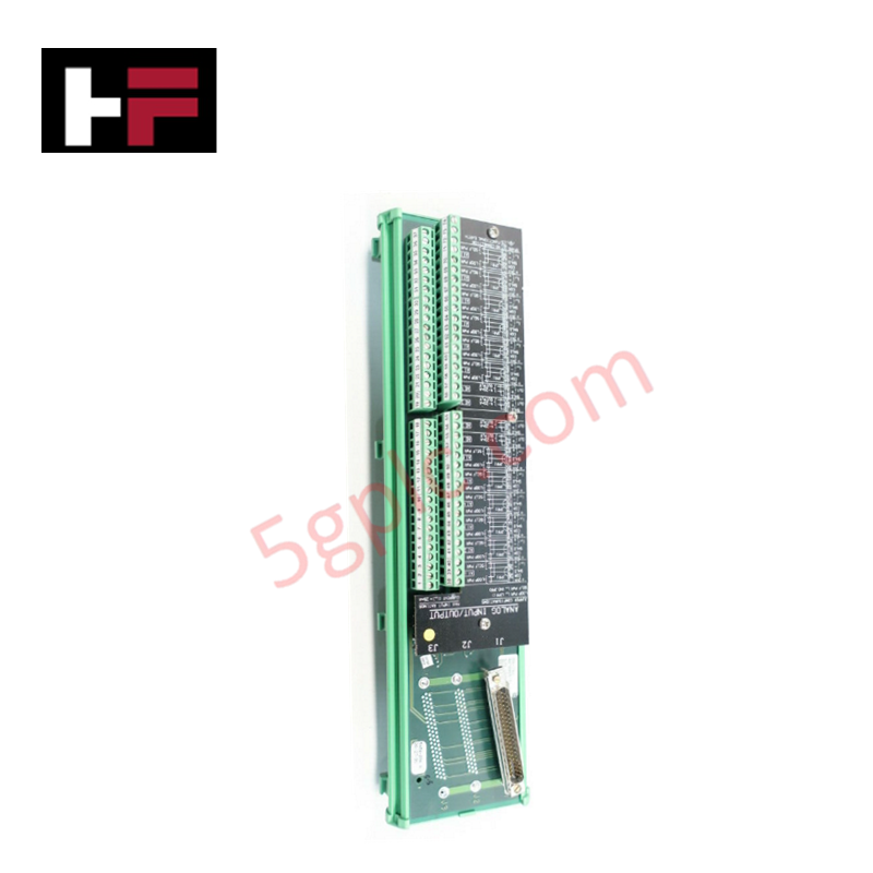
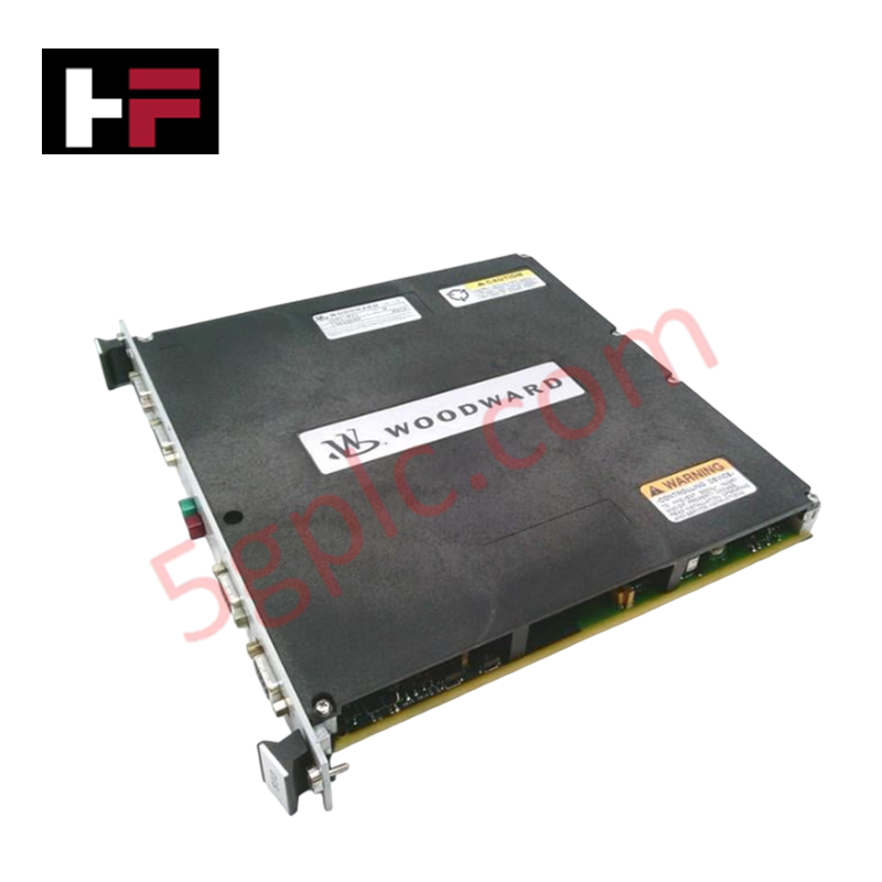
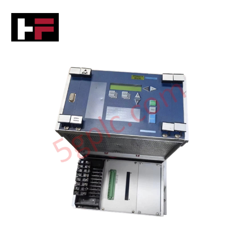
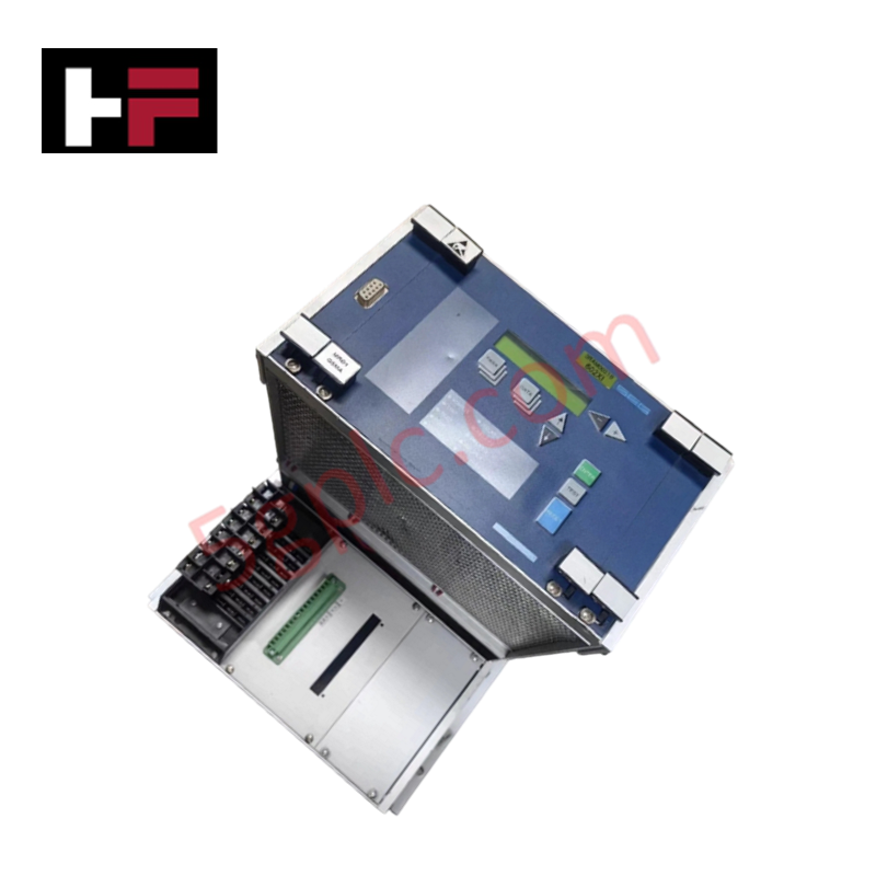
The Woodward CSC3GM1, also cataloged as the CSC3GM1 Signal Conditioning Module, operates as a dedicated hardware component for signal conversion and interfacing within turbine and generator control platforms. Operating on a nominal 24 VDC power supply across an operating temperature range of -20 deg C to +60 deg C, the module isolates input field signals to standard analog outputs. The single-channel hardware converts input ranges of +-10 V or 4-20 mA into standard analog outputs (4-20 mA or 0-10 V), maintaining signal integrity between field devices and central processing logic.
Hardware Specifications
| Parameter | Specification |
|---|---|
| Model | CSC3GM1 |
| Brand | Woodward |
| Origin | USA |
| Operating Temp | -20 deg C to +60 deg C |
| Power Consumption | 24 VDC Nominal |
| Signal Type | Current or voltage signal conditioning |
| Number of Channels | 1 channel per module |
| Input Signal Range | +-10 V, 4-20 mA (configuration dependent) |
| Output Signal Range | Standard analog output (4-20 mA or 0-10 V) |
| Isolation | Galvanic isolation between input and output |
| Mounting Method | DIN rail mountable |
Actuator Loop Feedback Response
The Woodward CSC3GM1 signal conditioning module utilizes low-latency analog conversion pathways designed to preserve actuator loop feedback response within high-speed governor loops. Galvanic isolation between the input channel and output circuitry suppresses common-mode ground loop current interference without introducing significant signal phase shift. Internal signal filtering prevents high-frequency electromagnetic noise from distorting continuous position and valve command signals transmitted to hydraulic actuators.
Frequently Asked Questions
Q: How is galvanic isolation maintained between the field input terminals and the internal logic rail?
A: Galvanic isolation is provided via an internal isolation transformer and optical coupling barrier. To prevent compromising this rating, field input signal wiring must be isolated from the module ground plane and routed independently of local power distribution lines.
Q: Does the module require field parameter calibration when switching between +-10 V and 4-20 mA input configurations?
A: Yes. Input channel range selection between +-10 V and 4-20 mA is hardware/dip-switch configuration dependent. Reconfiguring the input type requires zero and span calibration verification using calibrated current/voltage sources before re-engaging the module into an active loop.
Field Installation Guidelines
Mount the module on a standard DIN rail inside a protective metal panel, verifying that the DIN rail spring latch fully engages the mounting rail. Connect the 24 VDC power supply conductors to the designated terminals, observing correct polarity to prevent reverse voltage trip. Run all input (4-20 mA / +-10 V) and output signal cables using shielded twisted pairs, terminating the cable braid shield to the cabinet central grounding bus at one end only. Maintain physical separation between analog signal conduits and high-voltage AC lines to satisfy industrial EMI and EMC noise suppression standard requirements.
Additional Information
- 100% Genuine Parts: All products are original and authentic, ensuring reliable industrial performance.
- 30-Day Refund Guarantee: Return any in-stock item within 30 days in original, unopened packaging for a full refund (excluding shipping and fees).
- 12-Month Warranty: Covers defects in materials or workmanship; excludes misuse, normal wear, or unauthorized modifications.
- Worldwide Shipping: We ship via USPS, UPS, FedEx, and DHL. Delivery times vary by country and may be subject to customs or import fees.
- Support & Contact: Technical and warranty assistance is available anytime. Contact us here: Contact.
- Purchase Guidance: Check product specifications and compatibility carefully before ordering to ensure proper application.
Tech & Buying Guide

Will PLCs Become Obsolete? The Future of Control Systems in Industry 4.0
Modern manufacturing is undergoing a rapid technological transformation driven by Industry 4.0 innovations. Technologies like Artificial Intelligence (AI), Machine Learning (ML), and the Industrial Internet of Things (IIoT) are dominating discussions across the factory automation sector. Consequently, many engineers wonder if these advanced digital tools will eventually replace traditional Programmable Logic Controllers (PLCs). However, evaluating the core physics of industrial operations reveals a very different reality for control systems.

Demystifying Open Platform Communication (OPC): The Backbone of Industrial Interoperability
Interoperability remains a cornerstone requirement for modern smart factories and process automation. Open Platform Communication (OPC) bridges the gap between disparate hardware platforms, control systems, and visualization software. By establishing a universal communication standard, OPC allows field controllers, SCADA platforms, and enterprise software from different vendors to exchange real-time data seamlessly.

Understanding Siemens PLC Memory Cards: MMC, SMC, and SD Solutions in Industrial Automation
Memory management plays a pivotal role in maintaining control system reliability across modern manufacturing plants. Industrial control systems rely on specialized memory cards to store project logic, firmware updates, and retentive system data. Siemens uses several memory architectures, including Micro Memory Cards (MMC) and SIMATIC Memory Cards (SMC). Engineers must understand these hardware variations to ensure zero data loss and minimize downtime during maintenance routines.