










Product Details
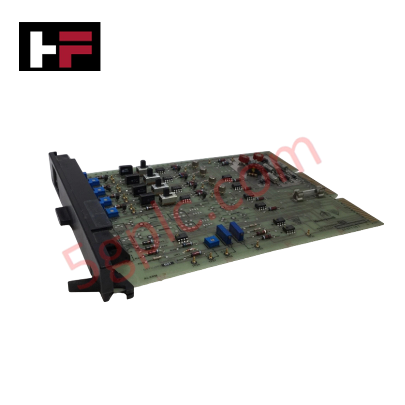
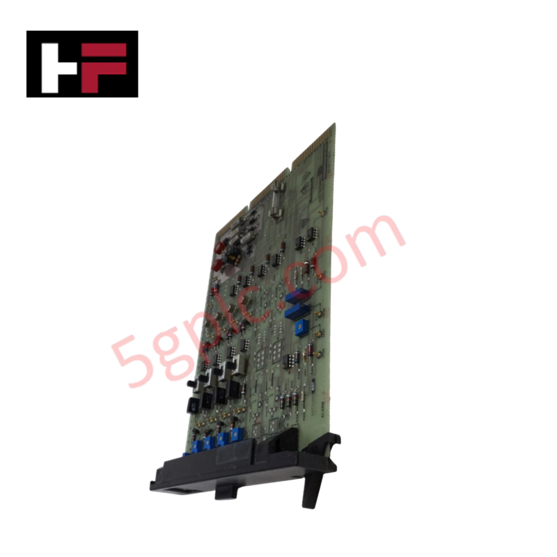
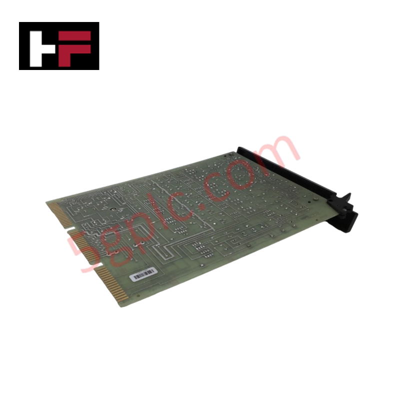
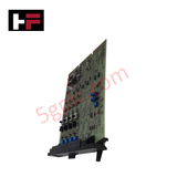
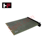
The Honeywell 62795604-001, also cataloged as the 62795604 Control Card Module Board, operates as a dedicated hardware component for high-speed signal processing and real-time control within Honeywell automation architecture platforms. The physical assembly executes local control loops and diagnostics, interfacing directly through the system backplane to handle discrete or analog instruction sets.
Hardware Specifications
| Parameter | Specification |
|---|---|
| Model | 62795604-001 |
| Brand | Honeywell |
| Origin | USA |
| Weight | 0.4 kg |
| Dimensions | 100 x 100 x 10 mm |
| Operating Temp | 0 to 60 deg C |
| Power Consumption | Rack backplane load dependent |
| Certification | CE |
Honeywell Channel-to-Channel Isolation Configuration
The card utilizes built-in channel-to-channel isolation architectures across its primary signal interfaces to isolate processing logic from field line disturbances. This internal electrical barrier limits potential cross-talk across adjacent signal paths and dampens high common-mode voltage spikes, ensuring that high-speed diagnostics remain accurate and uncorrupted under fluctuating plant loading conditions.
Frequently Asked Questions
Q: Does this control card module board support on-line hot-swap replacement procedures?
A: No, standard engineering safety protocols require the host system segment or chassis rack to be fully de-energized prior to removing or inserting this module to prevent structural backplane pin arcing.
Q: What is the maximum rated operational bandwidth for the onboard logic processing?
A: The card executes real-time control logic and high-speed diagnostic routines natively aligned with the standard cycle rates determined by the host Honeywell automation architecture.
Field Installation Guidelines
- Confirm total isolation of the host chassis power sources before attempting physical insertion of the board assembly.
- Slide the module strictly along the predefined enclosure card guides to maintain horizontal alignment and prevent pin deflection on the backplane connector.
- Ensure the outer metal frames or ground springs are properly seated to maintain chassis ground continuity and mitigate electrostatic discharge risks.
- Route low-voltage data cables independently from high-voltage active supply wires to minimize field electromagnetic coupling across the 100 x 100 x 10 mm envelope.
Additional Information
- 100% Genuine Parts: All products are original and authentic, ensuring reliable industrial performance.
- 30-Day Refund Guarantee: Return any in-stock item within 30 days in original, unopened packaging for a full refund (excluding shipping and fees).
- 12-Month Warranty: Covers defects in materials or workmanship; excludes misuse, normal wear, or unauthorized modifications.
- Worldwide Shipping: We ship via USPS, UPS, FedEx, and DHL. Delivery times vary by country and may be subject to customs or import fees.
- Support & Contact: Technical and warranty assistance is available anytime. Contact us here: Contact.
- Purchase Guidance: Check product specifications and compatibility carefully before ordering to ensure proper application.
Tech & Buying Guide

Demystifying PLC Memory: A Technical Guide to Architecture, Retention, and Performance
Modern industrial automation relies heavily on the reliability of programmable logic controllers (PLCs). At the heart of every PLC lies its memory system. This subsystem directly dictates scan times, program capacity, and data survival during power outages. For field engineers, understanding how a control system allocates, retains, and secures this memory is essential for writing efficient code and preventing costly downtime.

Executing a PLC System Site Acceptance Test (SAT): The Definitive Engineering Guide
The transition of a Programmable Logic Controller (PLC) cabinet from a controlled factory floor to a volatile plant environment represents a critical milestone in factory automation. While a Factory Acceptance Test (FAT) validates standalone hardware compliance under ideal conditions, it cannot replicate real-world process dynamics. Therefore, deploying an industrial automation system requires a rigorous Site Acceptance Test (SAT) to verify total loop integrity, field wiring wiring metrics, and process control parameters before final customer handover.

Advanced Integration: Master Protocol for VFD Commissioning and Testing
Deploying variable frequency drives (VFDs) requires precise execution during the initial commissioning phase. Junior automation engineers often find the first power-up sequence intimidating. However, following a rigorous engineering framework ensures equipment safety and system reliability. Proper startup procedures protect both the drive electronics and the connected motor.