










Product Details
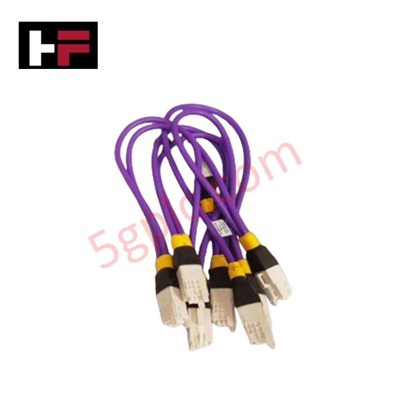
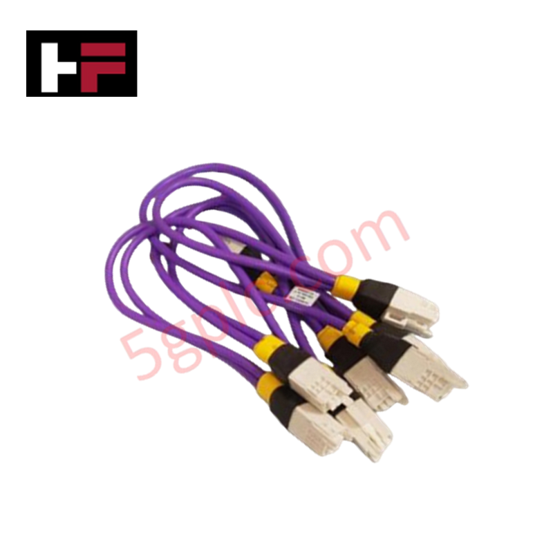
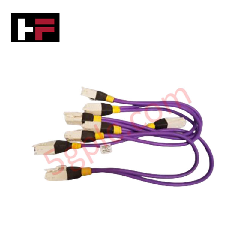
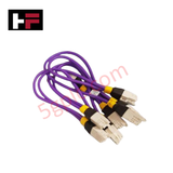
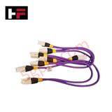
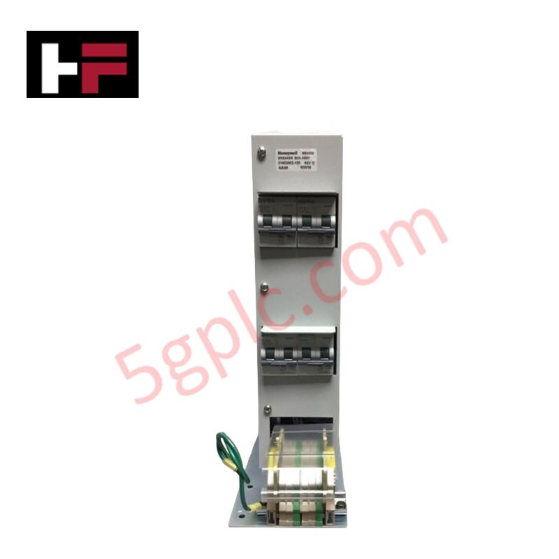
The Honeywell 51202971-512, also cataloged as the 51202971 Combo I/O Link Wire Harness, operates as a dedicated hardware component for direct physical/electrical signal routing within Honeywell Experion PKS and C300 controller systems. Configured for concurrent multi-wire input and output data loops, the assembly handles raw physical signal paths to preserve point-to-point transmission tracking between peripheral termination components and the central processing nodes.
Hardware Specifications
| Parameter | Specification |
|---|---|
| Model | 51202971-512 |
| Brand | Honeywell |
| Origin | USA |
| Weight | 0.3 kg |
| Dimensions | Standard multi-conductor industrial rack lengths |
| Operating Temp | -40 to 85 deg C |
| Power Consumption | Passive physical distribution assembly (Zero current draw) |
| Configuration | Multi-wire assembly supporting input and output paths |
| Connector Type | Industrial-grade harness connector |
| Wire Gauge | 22-18 AWG |
| Shielding | EMI/RFI shielded for noise immunity |
| Material | High-durability PVC and industrial-grade conductors |
Honeywell DCS Channel-to-Channel Isolation Parameters
The hardware assembly layout maintains factory channel-to-channel isolation parameters when mated with high-density C300 I/O modules. By utilizing internal physical grouping barriers and active EMI/RFI shielding configurations, the structure suppresses mutual inductive cross-talk across adjacent signal runs, preventing transient voltage spikes from affecting parallel measuring networks operating on the 4-20 mA HART loop protocol.
Frequently Asked Questions
Q: Can this combo I/O link harness be uncoupled while the C300 system is actively running loops?
A: No, decoupling the assembly during live runtime operations breaks continuous current loops, producing signal faults inside the processor registers and forcing downstream safety interlocks.
Q: How does the mixed 22-18 AWG internal wiring layout affect termination resistance?
A: The varied gauges match specific electrical load profiles for standard input and output circuits, keeping line impedance within baseline specification limits without causing thermal loading.
Field Installation Guidelines
- Install the shielded harness along distinct low-voltage industrial wireways, maintaining maximum physical isolation from high-voltage AC motor lines.
- Inspect the plug housing for contact alignment prior to slotting into the controller board receiver to avoid structural pin damage.
- Tighten all integrated mechanical locks or retaining screws until the connector face sits flush against the chassis grounding plate.
- Verify the shield continuity connection, terminating the overall drain wire directly to the master plant instrument ground busbar.
Additional Information
- 100% Genuine Parts: All products are original and authentic, ensuring reliable industrial performance.
- 30-Day Refund Guarantee: Return any in-stock item within 30 days in original, unopened packaging for a full refund (excluding shipping and fees).
- 12-Month Warranty: Covers defects in materials or workmanship; excludes misuse, normal wear, or unauthorized modifications.
- Worldwide Shipping: We ship via USPS, UPS, FedEx, and DHL. Delivery times vary by country and may be subject to customs or import fees.
- Support & Contact: Technical and warranty assistance is available anytime. Contact us here: Contact.
- Purchase Guidance: Check product specifications and compatibility carefully before ordering to ensure proper application.
Tech & Buying Guide

Comprehensive Guide to Instrumentation and Control (I&C) Design Basis
Instrumentation and Control (I&C) Design Basis serves as the foundational technical document for modern plant engineering. Project teams rely on this master specification to govern engineering deliverables across front-end engineering design (FEED) and detailed execution phases. A well-constructed I&C design basis ensures seamless integration among field instrumentation, safety systems, and main control systems. Furthermore, establishing clear technical standards early mitigates execution risks and prevents costly re-engineering during plant commissioning.

The Shift to Flexible IO Modules in Modern Industrial Automation
Traditional control systems rely on dedicated Input Output (IO) cards for industrial automation. Each conventional module processes a single signal type, such as Digital Input (DI), Digital Output (DO), Analog Input (AI), or Analog Output (AO). A standard 16-channel card accepts only one specific channel type across all ports. This inflexible hardware design often creates severe engineering bottlenecks during project execution. Engineers frequently must install entirely new cards to accommodate a single extra sensor. Consequently, late design changes increase control cabinet space requirements and drive up project costs.

DCS Commissioning Steps in Industrial Automation Projects
Commissioning a Distributed Control System (DCS) represents a crucial milestone when deploying modern process automation infrastructure. Field engineers must execute systematic verification steps to transition complex control hardware from static installation to dynamic plant control. Proper commissioning ensures that controllers, I/O modules, network switches, and HMI software operate in strict compliance with engineering design specifications before introducing live process fluids.