


Product Details
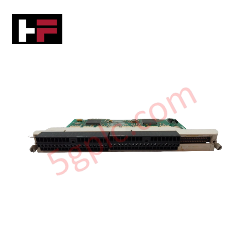
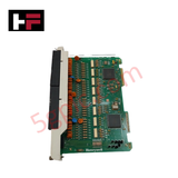
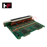
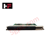
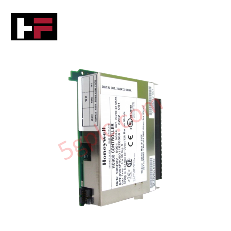
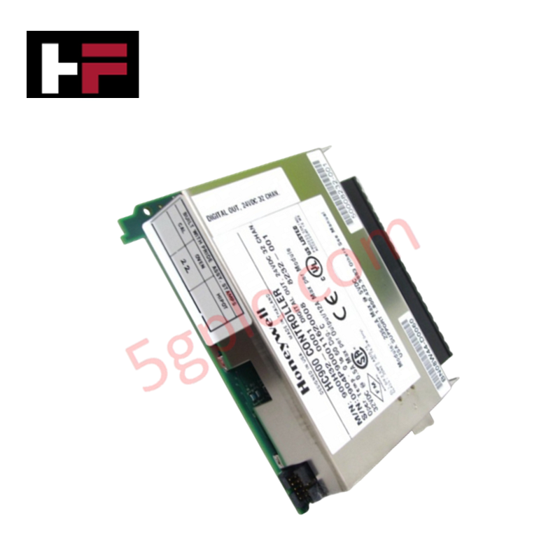
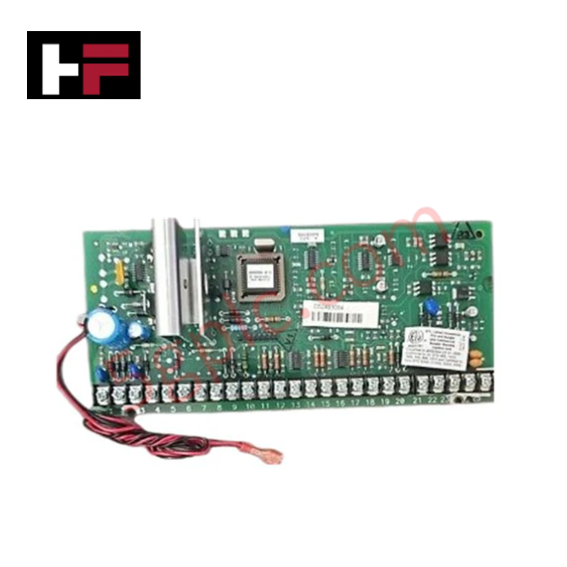
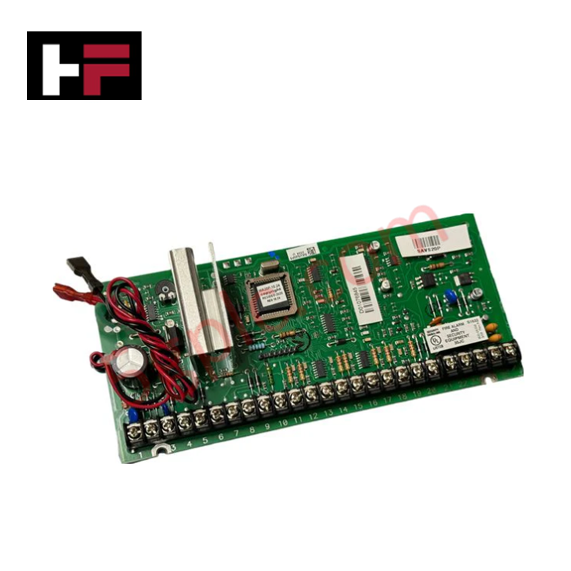
Configured for discrete signal acquisition within PLC control architectures, the Honeywell 621-3580R (621-3580R) input module PCB provides direct electrical execution of signal sensing for 24 VDC input loops. The module operates as a dedicated hardware component for converting field-side voltage states into logic-level signals recognizable by the control processor.
Hardware Specifications
| Parameter | Specification |
|---|---|
| Model | 621-3580R |
| Brand | Honeywell |
| Origin | Not specified |
| Weight | 0.45 kg |
| Dimensions | Standard PCB form factor |
| Operating Temp | Consult controller hardware manual |
| Power Consumption | Dependent on host rack backplane |
| Input Voltage Range | 18 VDC to 28 VDC |
| Input Current | 6 mA to 15 mA |
Channel-to-Channel Isolation and Signal Integrity
The 621-3580R input module PCB incorporates galvanic signal isolation to ensure the integrity of the process control loop. By providing channel-to-channel isolation, the module prevents ground loops and electrical interference from propagating between disparate field input circuits. This isolation is mandatory for maintaining signal accuracy when interfacing with field sensors that operate at varying reference potentials. Furthermore, the design supports stability in high-density I/O applications, ensuring that transient surges within one input channel do not influence the state detection of adjacent channels or the primary backplane data bus.
Frequently Asked Questions
Q: Does the 621-3580R support hot-swapping within the PLC rack?
A: Live removal and insertion are determined by the specific backplane version and controller firmware. Consult the system hardware service guide to verify if the rack slot permits hot-swapping without triggering a processor fault or communication drop.
Q: Is this PCB compatible with non-Honeywell termination blocks?
A: The module is designed to interface with standard Honeywell-specified rack connectors. Compatibility with third-party termination hardware is not guaranteed and may introduce impedance mismatches or physical connection failures.
Field Installation Guidelines
- Static Discharge Protection: Handle the PCB using electrostatic discharge (ESD) safe practices. Use a grounded wrist strap when removing the module from its protective packaging to prevent damage to integrated logic circuits.
- Backplane Insertion: Align the PCB guide rails with the chassis frame before engaging the backplane connector. Apply even pressure until the locking mechanism is fully seated to ensure a secure, low-resistance connection.
- Cable Shielding: Terminate cable shields at the cabinet's common ground rail to prevent electromagnetic interference from inducing signal noise on the 24 VDC input lines.
- Input Voltage Verification: Confirm that the field-side supply voltage remains within the 18 VDC to 28 VDC operating range. Voltages exceeding the upper limit will cause permanent damage to the input sensing components.
Additional Information
- 100% Genuine Parts: All products are original and authentic, ensuring reliable industrial performance.
- 30-Day Refund Guarantee: Return any in-stock item within 30 days in original, unopened packaging for a full refund (excluding shipping and fees).
- 12-Month Warranty: Covers defects in materials or workmanship; excludes misuse, normal wear, or unauthorized modifications.
- Worldwide Shipping: We ship via USPS, UPS, FedEx, and DHL. Delivery times vary by country and may be subject to customs or import fees.
- Support & Contact: Technical and warranty assistance is available anytime. Contact us here: Contact.
- Purchase Guidance: Check product specifications and compatibility carefully before ordering to ensure proper application.


Tech & Buying Guide

Why 24V DC Power Supplies Standardize Modern Industrial Automation
Industrial control cabinets worldwide rely on 24V DC as the universal power standard for field instrumentation, sensors, and controllers. Walk into any manufacturing plant, and you will find PLCs, human-machine interfaces (HMIs), and smart actuators running on extra-low voltage DC. Standardizing on 24V DC enhances operational safety, lowers cabinet footprint, and maintains steady control performance across factory networks.

Essential Motion Control Commands: A Practical Guide for Engineers
Automation engineers often rely on precise position and speed control to drive modern factory machinery. Modern industrial systems, such as Programmable Logic Controllers (PLCs) and Distributed Control Systems (DCS), depend heavily on standardized motion instructions. Mastering these commands ensures operational safety, protects mechanical components, and optimizes cycle times across production lines.

Mastering Modern Industrial Joystick Controls in Heavy Automation
Industrial joysticks play a pivotal role in human-machine interaction across heavy material handling and mobile hydraulics. These tactile controllers translate complex operator movements into precise electrical signals for PLCs, motion controllers, and DCS networks. Consequently, selecting and installing the right joystick architecture ensures operator safety, reduces fatigue, and optimizes equipment performance.