


Product Details
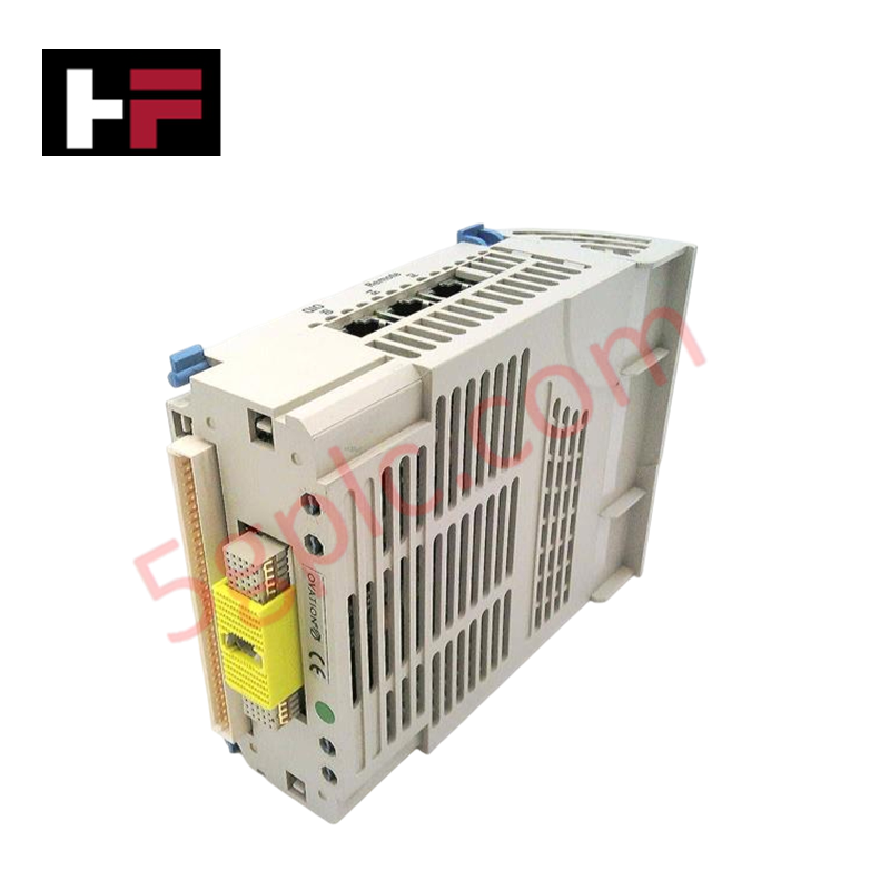
Configured for signal management in WDPF and Ovation control platforms, the Westinghouse 5X00226G04 (5X00226G04 I/O Interface Module) provides direct physical execution of I/O control and signal conditioning across industrial automation networks.
Hardware Specifications
| Parameter | Specification |
|---|---|
| Model | 5X00226G04 |
| Brand | Westinghouse |
| Origin | USA |
| Weight | Standard module weight |
| Dimensions | Chassis-dependent form factor |
| Operating Temp | 0 to 60 deg C |
| Power Consumption | System-dependent load |
| Operating Voltage | 24 VDC or 125 VDC |
| Mounting | DIN Rail or Rack Mount |
4-20 mA HART Loop Protocol
The 5X00226G04 module supports signal conditioning functions necessary for interfacing field devices with legacy Westinghouse WDPF or Ovation DCS architectures. Each module facilitates configurable input/output point management, allowing for specific analog or digital signal processing as dictated by the system loop requirements. The hardware maintains electrical compatibility with standard process control signals, ensuring channel integrity during high-speed data acquisition. The module design incorporates isolation characteristics to prevent potential ground faults in the field-side loop from impacting the primary control network communication, which utilizes proprietary Westinghouse protocols or standardized RS-485 interfaces.
Frequently Asked Questions
Q: Can the 5X00226G04 be hot-swapped while the DCS rack is powered?
A: Module replacement should be conducted only after inhibiting the associated I/O points in the engineering workstation software. Confirm the system is not actively executing control logic on the specific channels to prevent process transients during physical removal.
Q: How is the operating voltage (24 VDC vs 125 VDC) configured for this module?
A: The operating voltage is board-specific and determined by the hardware version or internal jumper configuration. Verify the module labeling and system documentation against the field supply voltage before applying power to prevent permanent damage to the I/O interface circuits.
Field Installation Guidelines
- De-energize the rack or module slot power prior to physical installation to ensure circuit protection.
- Align the module with the chassis guide rails and seat the backplane connector firmly to establish the required data and power interface.
- Terminate field signal wiring according to the specific loop diagram for the I/O channel configuration, ensuring all connections are tightened to the terminal strip.
- Verify that the shield drain wires for all signal cables are properly connected to the system ground bus to mitigate electromagnetic interference (EMI).
- Confirm correct module operation by checking the status indicators on the faceplate through the DCS control interface after commissioning the power.
Additional Information
- 100% Genuine Parts: All products are original and authentic, ensuring reliable industrial performance.
- 30-Day Refund Guarantee: Return any in-stock item within 30 days in original, unopened packaging for a full refund (excluding shipping and fees).
- 12-Month Warranty: Covers defects in materials or workmanship; excludes misuse, normal wear, or unauthorized modifications.
- Worldwide Shipping: We ship via USPS, UPS, FedEx, and DHL. Delivery times vary by country and may be subject to customs or import fees.
- Support & Contact: Technical and warranty assistance is available anytime. Contact us here: Contact.
- Purchase Guidance: Check product specifications and compatibility carefully before ordering to ensure proper application.


Tech & Buying Guide

Navigating Industrial Automation Failures: Types, Causes, and Mitigation Strategies
Modern manufacturing relies heavily on automated control systems to maximize throughput and maintain product quality. However, unplanned downtime in industrial automation can cost facility operators thousands of dollars per hour. Understanding how programmable logic controllers (PLCs), distributed control systems (DCS), and field instrumentation fail empowers engineering teams to implement robust preventive maintenance strategies.

Essential Motion Control Commands: A Practical Guide for Engineers
Automation engineers often rely on precise position and speed control to drive modern factory machinery. Modern industrial systems, such as Programmable Logic Controllers (PLCs) and Distributed Control Systems (DCS), depend heavily on standardized motion instructions. Mastering these commands ensures operational safety, protects mechanical components, and optimizes cycle times across production lines.

The Role of Intrinsic Safety Barriers in PLC and DCS Architectures
Implementing robust protection in hazardous industrial environments represents a fundamental safety requirement in factory automation. Process facilities often handle volatile gases, dusts, and chemical agents that pose significant combustion risks. Consequently, control system engineers must deploy energy-limiting interfaces to isolate safe-area control cabinets from hazardous-area field instrumentation. This article examines the function, selection, and electrical principles of intrinsic safety barriers within modern PLC and DCS networks.